Control apparatus for load device, and vehicle

a technology of load device and control apparatus, which is applied in the direction of relays, electric devices, transportation and packaging, etc., can solve the problems of reducing the operational particularly revealing fluctuations of the withstand voltage of the inverter element, and reducing the efficiency of the inverter when the stoppage of the inverter is stopped, so as to achieve the effect of expanding the temperature rang

Active Publication Date: 2010-02-25
DENSO CORP
View PDF8 Cites 23 Cited by
  • Summary
  • Abstract
  • Description
  • Claims
  • Application Information

AI Technical Summary

Benefits of technology

[0007]An object of the present invention is to provide a control apparatus for a load device, capable of more enlarging an inverter usable temperature range while securely protecting an inverter, and a vehicle provided with the control apparatus.
[0020]According to the present invention, the upper limit value of the voltage to be applied to the inverter is set according to the change in withstand voltage of the switching element constituting the inverter in association with the temperature, thus more enlarging a temperature range in which the inverter can be used while securely protecting the inverter.

Problems solved by technology

However, Japanese Patent Laying-Open No. 5-15068 nowhere particularly discloses fluctuations of the withstand voltage of the inverter element in association with a change in temperature of the inverter element.
In a case of such protection of the overvoltage, a voltage in excess of the withstand voltage of the inverter element is applied to the inverter when the inverter is at a low temperature: in contrast, it is construed that the stoppage of the inverter degrades operational efficiency of the inverter even if a voltage sufficiently lower than the withstand voltage of the inverter element is input when the inverter is at a high temperature.

Method used


Image

  • Control apparatus for load device, and vehicle
  • Control apparatus for load device, and vehicle
  • Control apparatus for load device, and vehicle

Examples


first embodiment

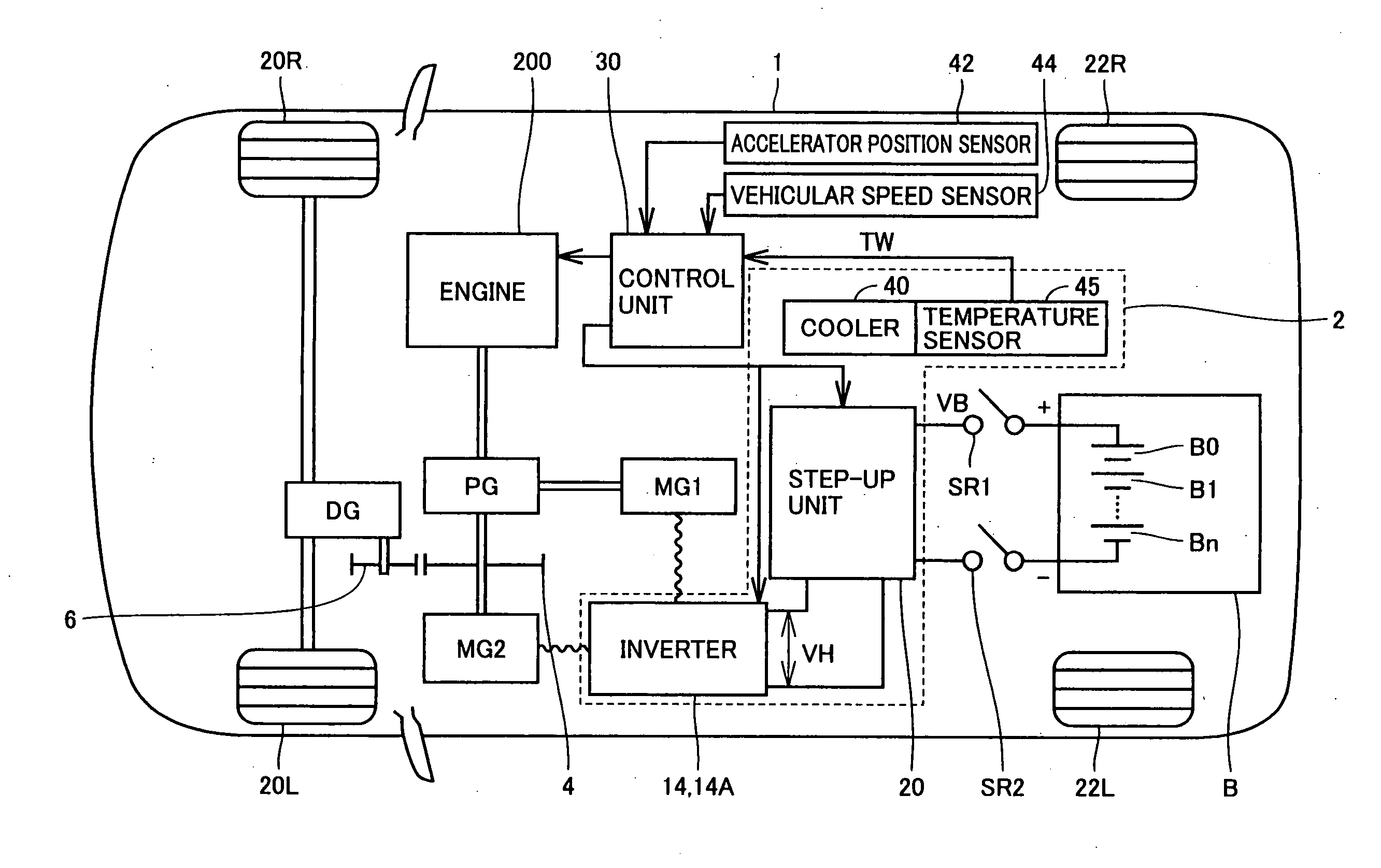
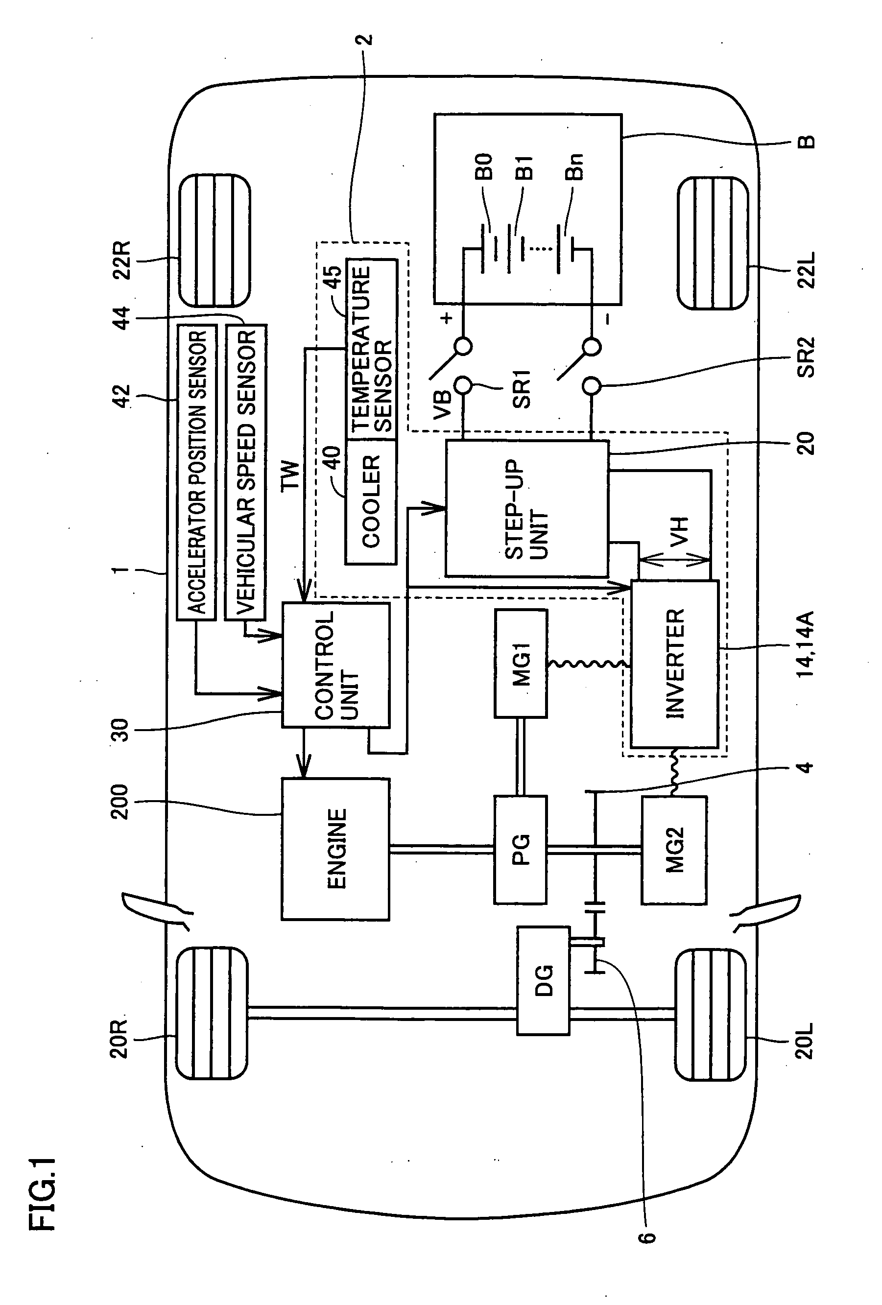
[0039]FIG. 1 is a block diagram illustrating the configuration of a vehicle having a control apparatus for a load device mounted thereon in a first embodiment according to the present invention.

[0040]With reference to FIG. 1, a vehicle 1 is a hybrid automobile. Vehicle 1 includes front wheels 20R and 20L, rear wheels 22R and 22L, an engine 200, a planetary gear PG, a differential gear DG and gears 4 and 6.

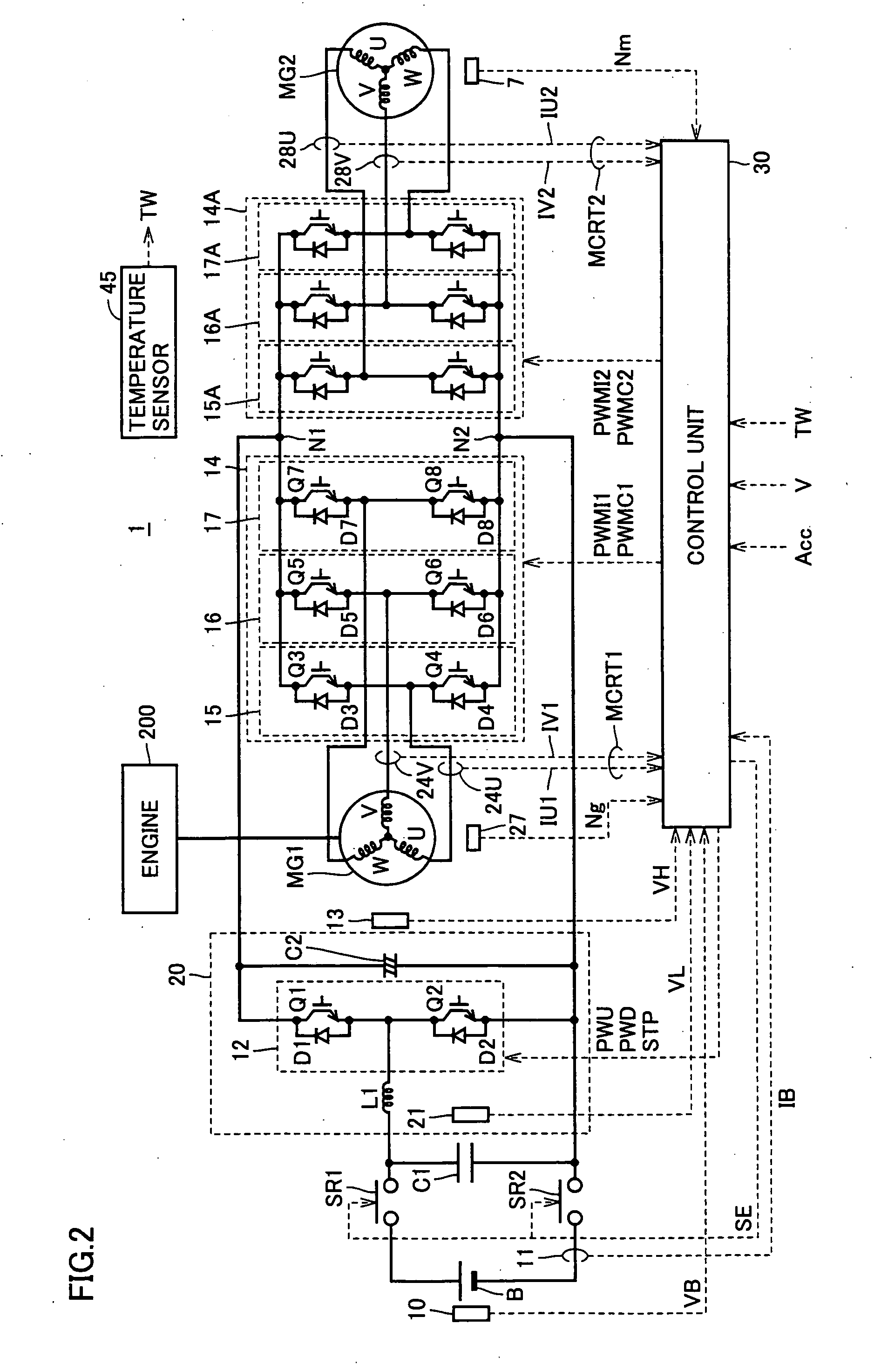
[0041]Vehicle 1 further includes a battery B and a voltage converting unit 2. Voltage converting unit 2 includes a step-up unit 20 for stepping up a DC voltage output from battery B, inverters 14 and 14A for supplying or receiving a DC electric power to or from step-up unit 20, a cooler 40 and a temperature sensor 45.

[0042]Vehicle 1 further includes a motor generator MG1 for generating power upon receipt of power from engine 200 via planetary gear PG and a motor generator MG2 having its rotation shaft connected to planetary gear PG. Inverters 14 and 14A are connected to each of mot...

second embodiment

[0097]The configuration of a vehicle having a control apparatus for a load device mounted thereon in a second embodiment is identical to that of vehicle 1 illustrated in FIG. 1. Furthermore, the configuration of a control system of a voltage converting unit 2 in the second embodiment is identical to that illustrated in FIG. 4. In the second embodiment, a control unit 30 limits loads of motor generators MG1 and MG2 when the temperature of an inverter becomes high.

[0098]FIG. 8 is a flowchart illustrating control processing executed by control unit 30 for the load device in the second embodiment.

[0099]With reference to FIGS. 8 and 7, processings in steps S1 to S4 illustrated in FIG. 8 are identical to those in the corresponding steps in the flowchart in FIG. 7. In the flowchart of FIG. 8, processing in step S4A is executed after the processing in step S3. This point is different from the flowchart of FIG. 7.

[0100]In step S4A, control unit 30 limits torques of motor generators MG1 and M...

third embodiment

[0102]In a third embodiment, the temperature of an inverter is estimated in a case of occurrence of abnormality in a temperature sensor, and then, an upper limit value VLM is set based on an estimation result. As a consequence, the inverter can be continuously operated even in a case of the occurrence of the abnormality in the temperature sensor.

[0103]The entire configuration of a vehicle having a control apparatus for a load device mounted thereon in the third embodiment is identical to that of vehicle 1 illustrated in FIG. 1. Here, as illustrated in FIG. 9, the third embodiment is different from the first and second embodiments in the point that a vehicle 1 is further provided with an alarm lamp 80 which is lighted in response to a signal EMG output from a control unit 30.

[0104]Next, with reference to FIGS. 10 and 4, description will be made on the configuration of a control system of a voltage converting unit 2 (see FIG. 1) in the third embodiment.

[0105]A voltage control unit 70A...


PUM


Abstract

A control apparatus for a load device mounted on a vehicle is provided with: a temperature sensor detecting a temperature of an inverter; a voltage sensor detecting an applied voltage of the inverter; and a control unit operating the inverter in a case where the applied voltage is a predetermined upper limit value or lower whereas stopping the inverter in a case where the applied voltage is higher than the upper limit value based on a voltage detection result by the voltage sensor. The control unit sets the upper limit value based on temperature dependency of a withstand voltage of an IGBT element included in the inverter and a temperature detection result by the temperature sensor.

Description

TECHNICAL FIELD[0001]The present invention relates to a control apparatus for a load device, and a vehicle and, more particularly, to a control apparatus for a load device provided with an inverter, capable of protecting the inverter from an overvoltage in the load device, and a vehicle provided with the control apparatus.BACKGROUND ART[0002]In recent years, attention has focused on a hybrid vehicle and an electric vehicle as environmentally friendly automobiles. A hybrid vehicle is an automobile that uses a motor to be driven by a DC power source via an inverter as a power source in addition to a conventional engine. Specifically, the power source is secured by driving the engine, and further, a DC voltage supplied from the DC power source is converted into an AC voltage by the inverter, and then, another power source is secured by rotating the motor at the converted AC voltage.[0003]In contrast, the electric vehicle is an automobile that uses a motor to be driven by a DC power sou...

Claims


Application Information

Patent Timeline
Patent Type & Authority Applications(United States)
IPC IPC(8): B60L1/00B60L50/16
CPCB60L3/12B60L2240/36Y02T10/642H02M1/32H02P27/08B60L2240/525Y02T10/64
Inventor MITSUTANI, NORITAKE
Owner DENSO CORP
Why Eureka
Try Eureka