Detector

a detector and detector technology, applied in the field of inductive detectors, can solve the problems of inability to distinguish between a user's finger and a water droplet, prohibitively expensive, and not particularly reliable or safe for many applications, and achieve the effect of small deflection

Inactive Publication Date: 2010-02-25
MICROCHIP TECH INC
View PDF7 Cites 51 Cited by
  • Summary
  • Abstract
  • Description
  • Claims
  • Application Information

AI Technical Summary

Benefits of technology

[0016]Preferably the small deflections caused by a user's input are amplified using a lever arrangement.

Problems solved by technology

Such push buttons generally work well but suffer from reliability problems in harsh environments where foreign matter such as water, condensation, dirt or grease, can interfere with the electrical contacts.
There are particular problems in some environments such as petrochemical plants or mines where the spark from an electrical contact may cause an explosion.
Whilst overcoming the traditional problems with electrical contacts, capacitive sensors are typically unable to differentiate between a user's finger or a water droplet, for example.
As such, they are not especially reliable or safe for many applications such as kitchen appliances or industrial systems where foreign matter near to the user interface is common.
There are further problems regarding temperature drift and typically each input requires its own electronic circuit local to each sensing point.
This can be prohibitively expensive in many applications that require a multiplicity of input points.
Such infra red systems can differentiate between a user's finger and a water droplet, for example, but they are expensive and need a transparent panel such as glass or plastic between switch and user.
The cost of the relatively complex electronics circuit is prohibitively expensive in some applications and the use of a relatively low modulation frequency limits speed of operation.
Furthermore, the invention requires relatively sophisticated and hence expensive, multi-layer winding arrangements at the sensing area.

Method used


Image

  • Detector
  • Detector
  • Detector

Examples


Embodiment Construction

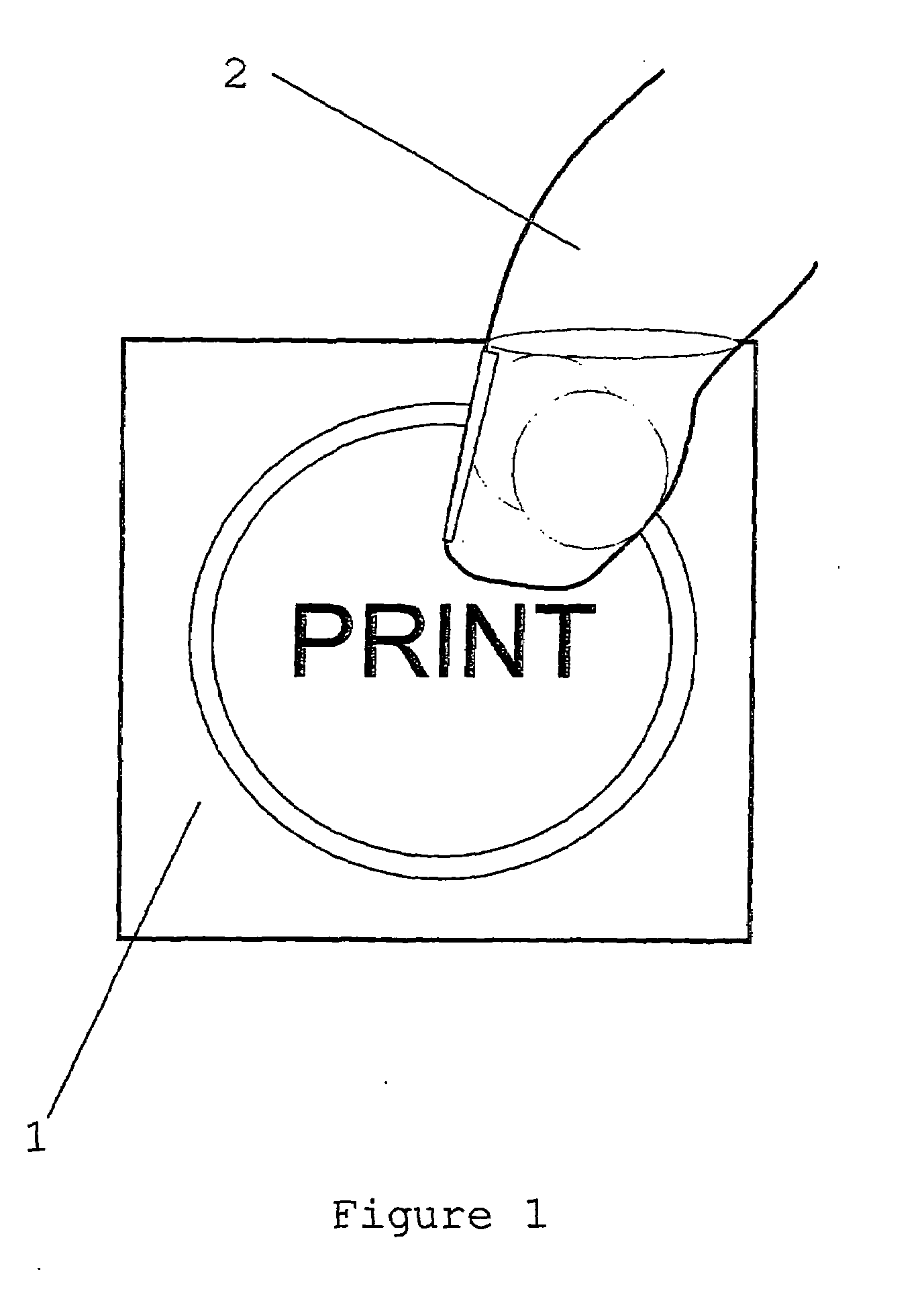
[0037]FIG. 1 shows a plan view of a man-machine interface push button. In this case a printer button is used as an example. A substantially impermeable, protective fascia panel [1] is printed with user instructions. The panel is formed by an injection moulding of a glass filled polymer such as nylon. The panel protects the inside of the printer from the external environment for reasons of safety, hygiene and reliability. A user's finger [2] presses down on the panel [1]. The detector is located behind the push button but is not shown here for clarity. Only one push button is shown in FIG. 1 for reasons of clarity but usually, several push buttons are located on a keyboard or control panel.

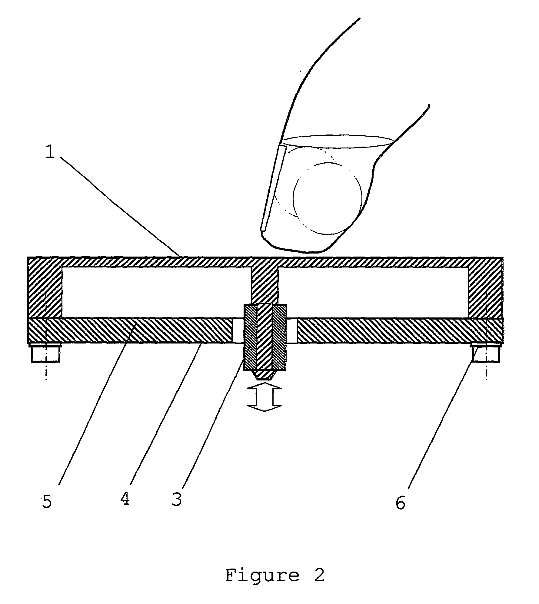
[0038]FIG. 2 shows a sectional view of a preferred embodiment of the man-machine interface push button in which an EID [3] is secured to a panel [1] by heat staking. Preferably, the ED [3] is a ferrite or alternatively, an electrically conductive element such as a copper cylinder. Any deflection of...


PUM


Abstract

A device for measuring the position of a first body relative to a second body comprising: a first body which further comprises an electrical intermediate device; a second body which further comprises at least two inductors energised with an alternating current and at least one of which is formed by a planar spiral winding on a printed circuit board normal to the measurement axis and attached to the second body; arranged such that displacement of the electrical intermediate device causes a change in inductance of the planar spiral winding and whereby measurement of the ratio of the inductances indicates the position of the first body relative to the second.

Description

FIELD OF THE INVENTION [0001]This invention relates to an inductive detector operable to measure the relative displacement of two or more bodies which has particular, but not exclusive, relevance to user elements in man-machine interfaces.REVIEW OF THE ART KNOWN TO THE APPLICANT [0002]A common position detector or user element in man-machine interfaces is the push button. Push buttons typically detect a user's input by making or breaking electrical contacts. Such push buttons generally work well but suffer from reliability problems in harsh environments where foreign matter such as water, condensation, dirt or grease, can interfere with the electrical contacts. There are particular problems in some environments such as petrochemical plants or mines where the spark from an electrical contact may cause an explosion.[0003]Capacitive detectors or switches have been utilised to overcome many of the problems associated with electrical contacts. In this type of switch, the change in capaci...

Claims


Application Information

Patent Timeline
Patent Type & Authority Applications(United States)
IPC IPC(8): H03K17/97G01D5/22
CPCG01D5/202G01D5/2013
Inventor HOWARD, MARK ANTHONYKREIT, DARRAN
Owner MICROCHIP TECH INC
Why Eureka
Try Eureka