Wick for an anesthetic evaporator

a technology of anesthetic evaporators and wicks, which is applied in the direction of respirators, inhalators, etc., can solve the problems that the wick tube and the anesthetic evaporator can be manufactured at a high cost and require a rather substantial manufacturing effort, so as to improve the utilization of space, reduce flow resistance, and smooth the surface

Inactive Publication Date: 2010-03-04
DRAGERWERK AG
View PDF17 Cites 11 Cited by
  • Summary
  • Abstract
  • Description
  • Claims
  • Application Information

AI Technical Summary

Benefits of technology

[0010]The advantage of the present invention is the design of the wick as a preferably one-piece, porous, dimensionally stable wick body, which can be directly connected to the corresponding connection component of the anesthetic evaporator. It is especially advantageous according to the invention to make gas ducts for passing through breathing gas in one piece with the wick body. The gas ducts are formed by webs, which are arranged either on the outside or on the inside of the wick body and are preferably manufactured as one assembly unit with the wick body. The gas ducts preferably extend helically at the wick body. However, routing the gas via a plurality of gas ducts, which are located one on top of another and are connected to each other, is possible as well. The wick body is preferably designed as a hollow cylinder or as a solid cylinder.
[0011]Other advantages of the wick according to the present invention are improved space utilization within the anesthetic evaporator, smoother surfaces to reduce flow resistances, simpler mounting and better thermal coupling of the wick body with the compensator of the anesthetic evaporator, with which the temperature effect is compensated.
[0012]It is especially advantageous that the wick body according to the present invention including the gas ducts can be manufactured from one piece. It may be an injection molding manufactured in a mold or a sintered shaped wick part. The gas-carrying area is formed here by a helical recess in the form of a groove in the shaped wick part. The liquid transport takes place by capillary action within the porous material. The capillary action can be varied by varying the density and the thickness of the wick body. As an alternative, the wick body may also be manufactured as a foam part or foamed part. Materials that are resistant to the anesthetics used are to be selected as the material for the wick body. Especially suitable are polyethylene, polypropylene, polytetrafluoroethylene, polyamide, special steel or even mixtures of these materials. Depending on the anesthetic used, bronze, copper, brass as well as sintered glass or sintered ceramic materials are suitable as well. The wick body is manufactured such that a sintered material is pressed from a preferably spherical granular product. The sintered compact is dimensioned such that its mean or typical pore size has a value of less than or equal to 30 μm. As an alternative to granular material, the wick body may also consist of an agglomeration of fine wires or fiber-like materials.
[0013]It is especially advantageous to arrange sealing lips, which come into contact either with the evaporator pot in the case of webs located on the outside or with the wick holder in case of webs located on the inside or with the compensator, at the webs pointing outwardly or inwardly, with which the gas ducts are formed. Gas tightness of the gas-carrying ducts against the evaporator pot or the wick holder or compensator is achieved in this manner so that the gas flows all the way through the gas ducts rather than flowing past the gas ducts at right angles to the longitudinal axis. Improvement of anesthetic uptake can be achieved by arranging obstacles within the gas ducts, because a turbulent flow develops as a result.
[0014]Gas-carrying ducts are provided within the wick body in another advantageous embodiment in order to enrich the gas flow with anesthetic vapor. Since the gas-carrying ducts are surrounded by the wick material on all sides in this embodiment, especially good saturation with anesthetic vapor is achieved.
[0015]One exemplary embodiment of the present invention is shown in the figures and will be explained in more detail below. The various features of novelty which characterize the invention are pointed out with particularity in the claims annexed to and forming a part of this disclosure. For a better understanding of the invention, its operating advantages and specific objects attained by its uses, reference is made to the accompanying drawings and descriptive matter in which preferred embodiments of the invention are illustrated.

Problems solved by technology

A wick tube as is used in the prior-art anesthetic evaporator can be manufactured at a high cost and requires a rather substantial manufacturing effort.

Method used


Image

  • Wick for an anesthetic evaporator
  • Wick for an anesthetic evaporator
  • Wick for an anesthetic evaporator

Examples


Embodiment Construction

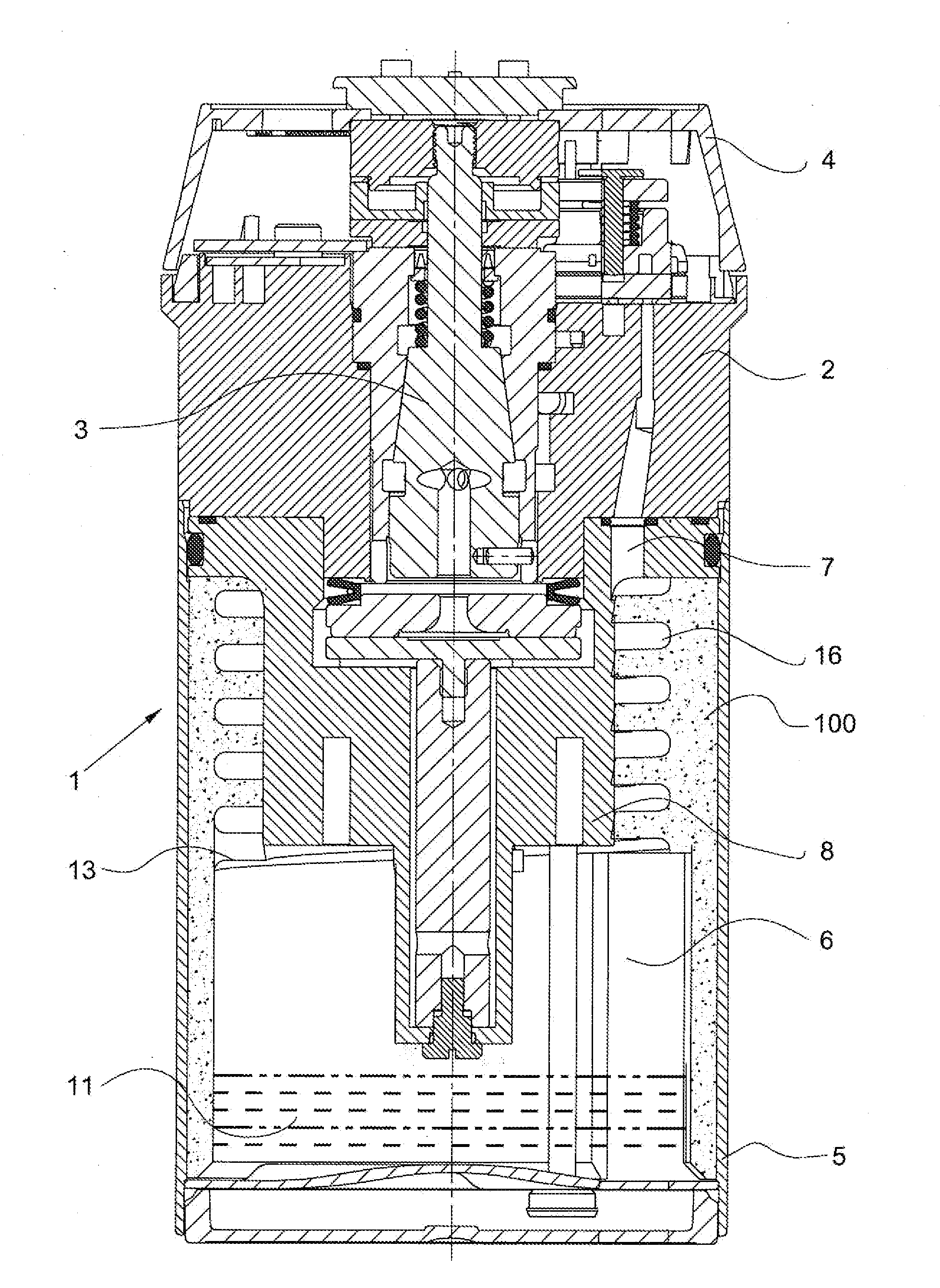
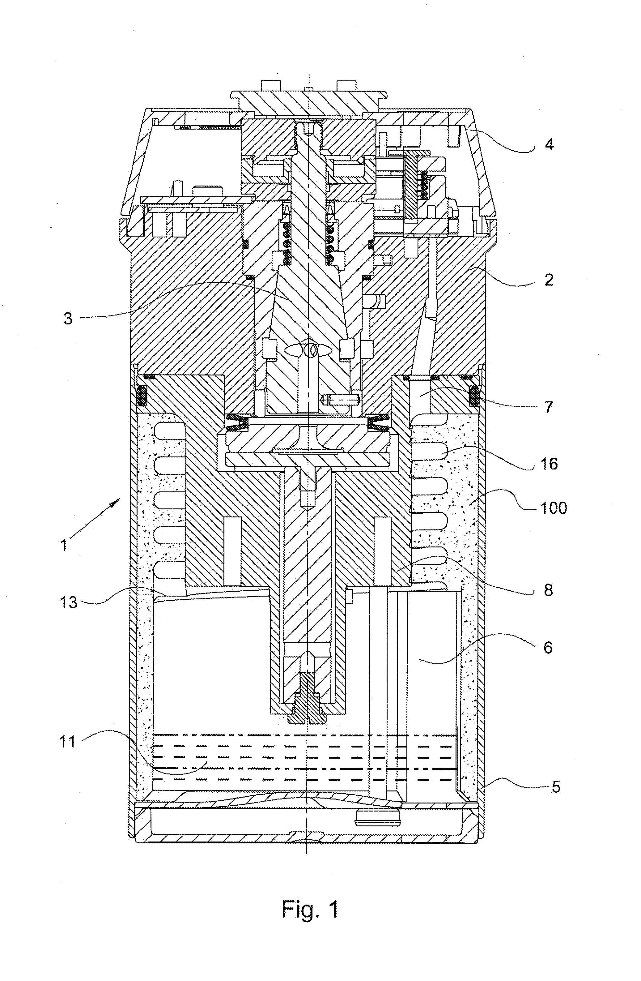
[0020]Referring to the drawings in particular, FIG. 1 schematically shows an anesthetic evaporator according to the invention. An evaporator pot 5 defines an evaporator chamber 6, The evaporator pot 5 is located under an evaporator upper part 2 with a dispensing cone 3 for dispensing breathing gas saturated with anesthetic vapor and with a setting wheel 4 connected to the dispensing cone 3. The invention provides an anesthetic evaporator wick structure 100 comprised of a cylindrical wick body (14, 21) and helically extending cavity 16 (shown schematically as a vertically extending box in FIG. 1) described below. The dimensionally stable wick body 14, 21 is porous and transports anesthetic by means of capillary force. The evaporator wick structure 100, namely the cylindrical wick body 14, 21 is designed in terms of its principal geometry as a hollow cylinder.

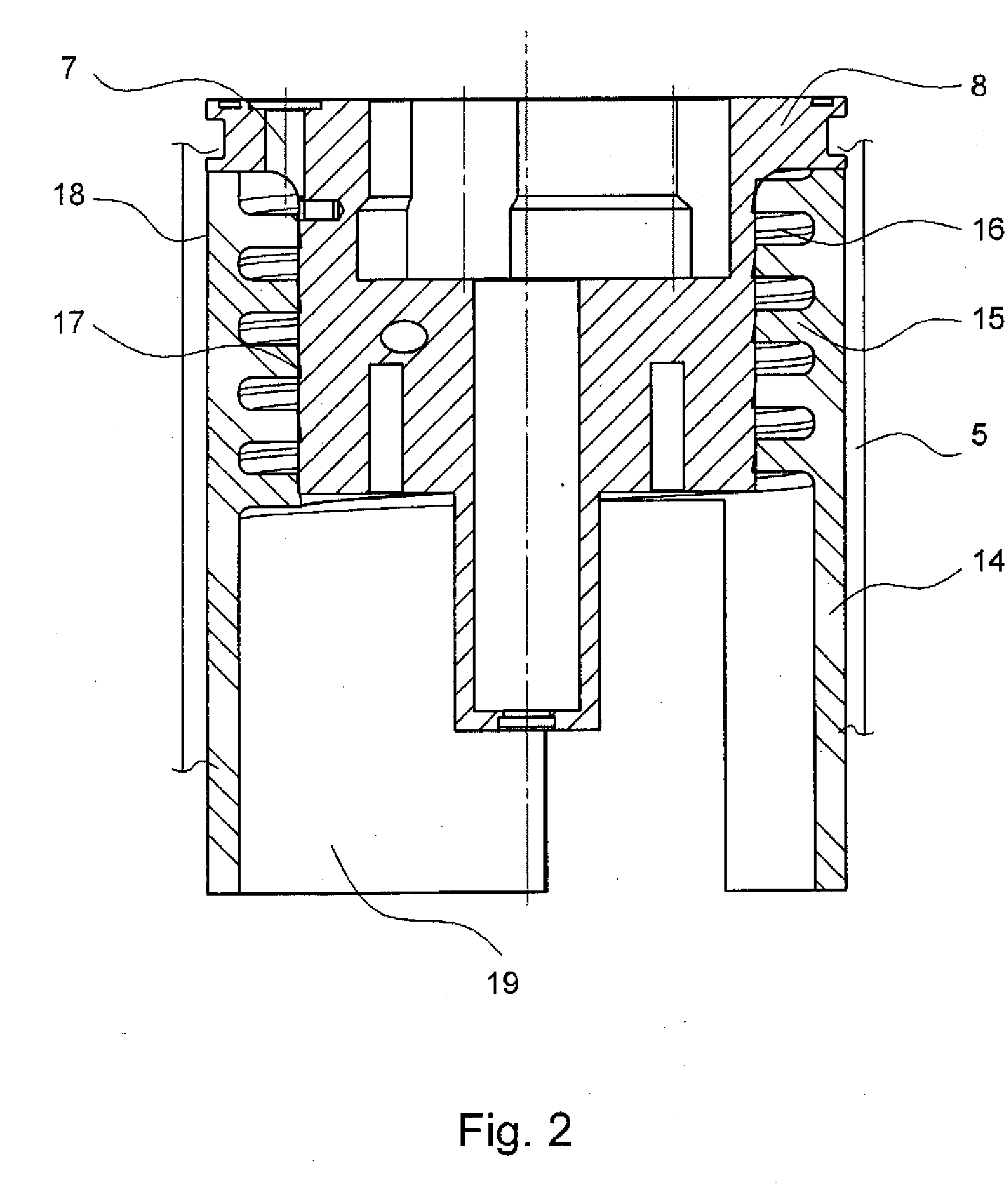
[0021]The anesthetic evaporator wick structure 100 is provided radially outwardly of a compensator 8 and extends into the evapo...


PUM


Abstract

A wick for an anesthetic evaporator is provided as a dimensionally stable wick body (14) transporting anesthetic by means of capillary force is provided. The wick body comprises a hollow cylinder as well as webs by which a gas-carrying cavity is formed.

Description

CROSS REFERENCE TO RELATED APPLICATIONS[0001]This application claims the benefit of priority under 35 U.S.C. §119 of German Patent Application DE 10 2008 045 081.2 filed Aug. 29, 2008, the entire contents of which are incorporated herein by reference.FIELD OF THE INVENTION[0002]The present invention pertains to a wick for an anesthetic evaporator.BACKGROUND OF THE INVENTION[0003]Anesthetic evaporators for dispensing anesthetics frequently operate according to the “bypass principle,” according to which a partial gas flow is branched off from a bypass line connecting the evaporator inlet and the evaporator outlet and is enriched with anesthetic vapor in an evaporator chamber. The partial gas flow enriched with anesthetic vapor is again mixed at the evaporator outlet with the gas flow flowing through the bypass line via a dispensing valve, which is connected to a setting wheel for setting the concentration of the anesthetic released. Helically arranged wick tubes, through which the par...

Claims


Application Information

Patent Timeline
Patent Type & Authority Applications(United States)
IPC IPC(8): A61M16/01
CPCA61M16/18
Inventor KLEINSCHMIDT, LOTHARGIPPERT, KARL-LUDWIGBRUHN, THORSTENREICHERT, DIRK-STEFANRIECKE, MICHAEL
Owner DRAGERWERK AG
Why Eureka
Try Eureka