Shield conductor and shield conductor manufacturing method

a shield conductor and manufacturing method technology, applied in the direction of power cables, paper/cardboard containers, cables, etc., can solve the problem of increasing the number of parts, and achieve the effect of improving the radiation performance of the shield conductor

Inactive Publication Date: 2010-03-04
AUTONETWORKS TECH LTD +2
View PDF7 Cites 36 Cited by
  • Summary
  • Abstract
  • Description
  • Claims
  • Application Information

AI Technical Summary

Benefits of technology

[0012]In addition, since a plurality of wires are enwrapped by a heat transfer member, the pipe's shape-following property to the outer circumference of the heat transfer member is improved by simplifying the outer circumferential shape of the heat transfer member, and eventually, the adhesion between the heat transfer member and the pipe is enhanced, thereby improving the radiation efficiency.

Problems solved by technology

As a protecting method for shielding members and wires in this kind of shield conductor, means for enwrapping shielding members with a protector made of synthetic resin has been generally known, however, using such protector causes a problem of increasing the number of parts.

Method used


Image

  • Shield conductor and shield conductor manufacturing method
  • Shield conductor and shield conductor manufacturing method
  • Shield conductor and shield conductor manufacturing method

Examples


embodiment 1

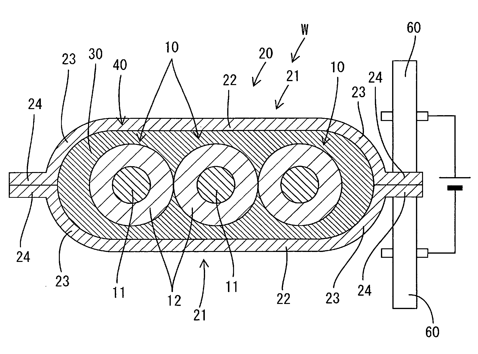
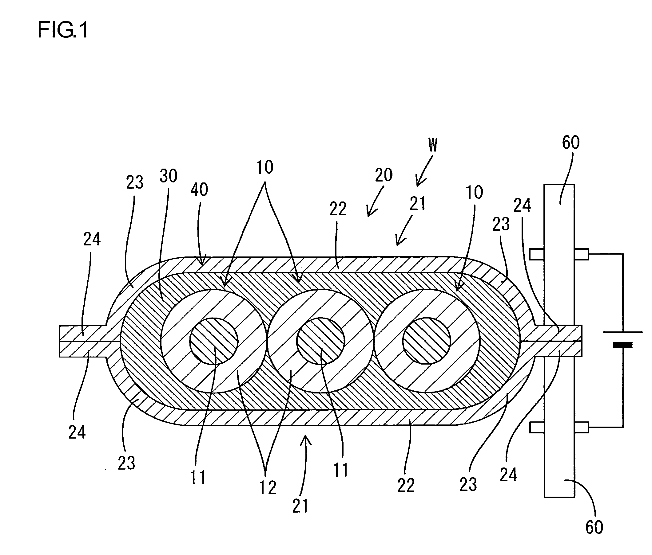
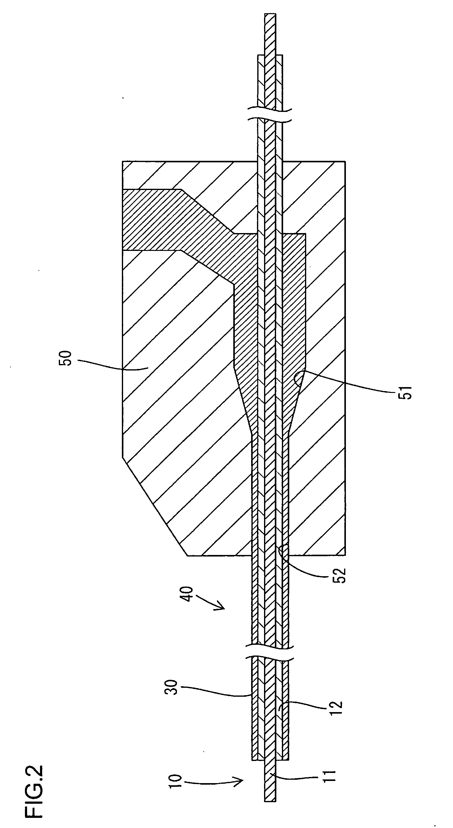
[0034]In what follows, as referring now to FIGS. 1 to 4, Embodiment 1 which materializes the present invention is described. A shield conductor W according to the present embodiment is placed, for example, between devices such as a battery, an inverter, and a motor (not shown) that compose a drive power source in an electric vehicle, and constituted in a manner that three wires 10 of non-shielded type are inserted into a pipe 20 which has both functions of collective shielding and protecting wire, with a heat transfer member 30 intervened in a clearance between the outer circumference of the wires 10 and the inner circumference of the pipe 20.

[0035]The wire 10 is formed by enwrapping the outer circumference of a metal conductor 11 (the metal is, for example, aluminum alloy and copper alloy) with an insulating coating 12 made of synthetic resin, and the conductor 11 is made of a single core wire or a twisted wire spirally twisting a plurality of thin wires (not shown). The cross-sect...


PUM

PropertyMeasurementUnit
thicknessaaaaaaaaaa
diameteraaaaaaaaaa
diameteraaaaaaaaaa

Abstract

A shield conductor W comprises: a plurality of wires 10, a heat transfer member 30 made of synthetic resin and formed so as to tightly attach to the outer circumference of the wires and moreover collectively enwrap the wires 10, and a metal pipe 20 assembled in a manner so as to tightly attach to the outer circumference of the heat transfer member 30. The heat generated in the wires 10 is transmitted from the outer circumference of the insulating coating 12 to the heat transfer member 30, then transmitted within the heat transfer member 30, and then transmitted from the outer circumferential surface of the heat transfer member 30 to the inner circumference of the pipe 20, and is finally released to the air from the outer circumference of the pipe 20.

Description

TECHNICAL FIELD [0001]The present invention relates to a shield conductor and a shield conductor manufacturing method.BACKGROUND ART [0002]As a shield conductor using a non-shielded wire, collectively shielding a plurality of non-shielded wires by enwrapping with a shielding member composed of a tubular braided wire made of metal thin wires woven into meshes is known. As a protecting method for shielding members and wires in this kind of shield conductor, means for enwrapping shielding members with a protector made of synthetic resin has been generally known, however, using such protector causes a problem of increasing the number of parts.[0003]Considering the foregoing, the applicant of the present application has suggested, as described in Patent Literature 1, a structure wherein a non-shielded wire is inserted into a metal pipe. According to this configuration, the pipe fulfills functions of shielding and protecting wires, and it is therefore advantageous because this configurati...

Claims


Application Information

Patent Timeline
Patent Type & Authority Applications(United States)
IPC IPC(8): H01B7/42B32B37/02
CPCY10T156/10H01B7/428
Inventor WATANABE, KUNIHIKONAKAGAKI, KAZUYUKISONODA, FUJIO
Owner AUTONETWORKS TECH LTD
Why Eureka
Try Eureka