Efficient high-ampacity bowl-shaped tubular conductors

a high-ampacity, bowl-shaped technology, applied in the direction of bus-bar installation, electric cable installation, electrical apparatus, etc., can solve the problems of uneven heating of the bus-bar conductor, uneven current distribution through the phase conductor, etc., to reduce power loss, reduce skin effects, and improve thermal dissipation and current distribution

Active Publication Date: 2010-03-04
SQUARE D CO
View PDF17 Cites 23 Cited by
  • Summary
  • Abstract
  • Description
  • Claims
  • Application Information

AI Technical Summary

Benefits of technology

[0005]Aspects of the present disclosure are directed to a bus system for use in electrical distribution equipment, which includes generally bowl-shaped busbar conductors for mounting both vertically as well as horizontally for supplying very high amperage (above 2000 amps) alternating current to the electrical distribution system. Compared to prior-art busbar shapes, such as flat, L-shaped, and U-shaped conductors, the bowl-shaped busbar conductors of a phase can be fabricated from less copper, which is an expensive metal, achieve better thermal dissipation and current distribution, and mitigate skin effects and therefore reduce power losses. The bowl-shaped busbar conductors are also relatively stiffer than prior-art busbars.
[0006]A particular aspect of the present disclosure also reduces proximity effects on the conducting phases by imposing a vertically oriented magnetic shield made of carbon steel between adjacent pairs of vertical busbars. Proximity effects relate to the undesired tendency of current to favor the conductor surface proximate an adjacent phase conductor, resulting in uneven current distribution through the phase conductor and uneven heating of the busbar conductors. Skin effects exacerbate this proximity-effect phenomenon because electrical current already prefers to distribute itself at the surface of the conductor. The magnetic shield suppresses proximity effects and increases the overall efficiency of the busbars by promoting a more uniform and symmetrical current density through the conductors.
[0007]A pair of oppositely facing bowl-shaped conductors, each of whose cross sections resembles half of a hexagon or an open three-sided isosceles trapezoid, are separated by an air gap in both horizontal and vertical configurations, forming an octagonal cross section in which the air gaps form two sides of the octagon. The air gap increases cooling efficiency by natural convection by exposing more surface area of the conductors directly to the air flow within the cabinet in which the busbars are disposed. As a result, the overall temperature of the bus system is reduced. The pair of mirrored bowl-shaped conductors more closely approximates a circular cross section compared to prior-art shapes, forming smoother transitions between the bends of the conductors presented to the electrical current. These smooth transitions improve current distribution throughout the conductor, reducing skin effects. As a result of the improved thermal dissipation and the reduction in skin effects, the overall amount of copper or other conductive material needed for the busbars to support the same current rating as prior-art busbars is significantly reduced.
[0008]The present busbars are easily manufactured by making two 60 degree bends in the sides of a flat sheet of conductive material. This manufacturing process is repeatable for both the horizontal and vertical busbars, and avoids any expensive and time-consuming extrusion techniques.

Problems solved by technology

Proximity effects relate to the undesired tendency of current to favor the conductor surface proximate an adjacent phase conductor, resulting in uneven current distribution through the phase conductor and uneven heating of the busbar conductors.

Method used


Image

  • Efficient high-ampacity bowl-shaped tubular conductors
  • Efficient high-ampacity bowl-shaped tubular conductors
  • Efficient high-ampacity bowl-shaped tubular conductors

Examples


Embodiment Construction

[0018]Although the invention will be described in connection with certain aspects and / or embodiments, it will be understood that the invention is not limited to those particular aspects and / or embodiments. On the contrary, the invention is intended to cover all alternatives, modifications, and equivalent arrangements as may be included within the spirit and scope of the invention as defined by the appended claims.

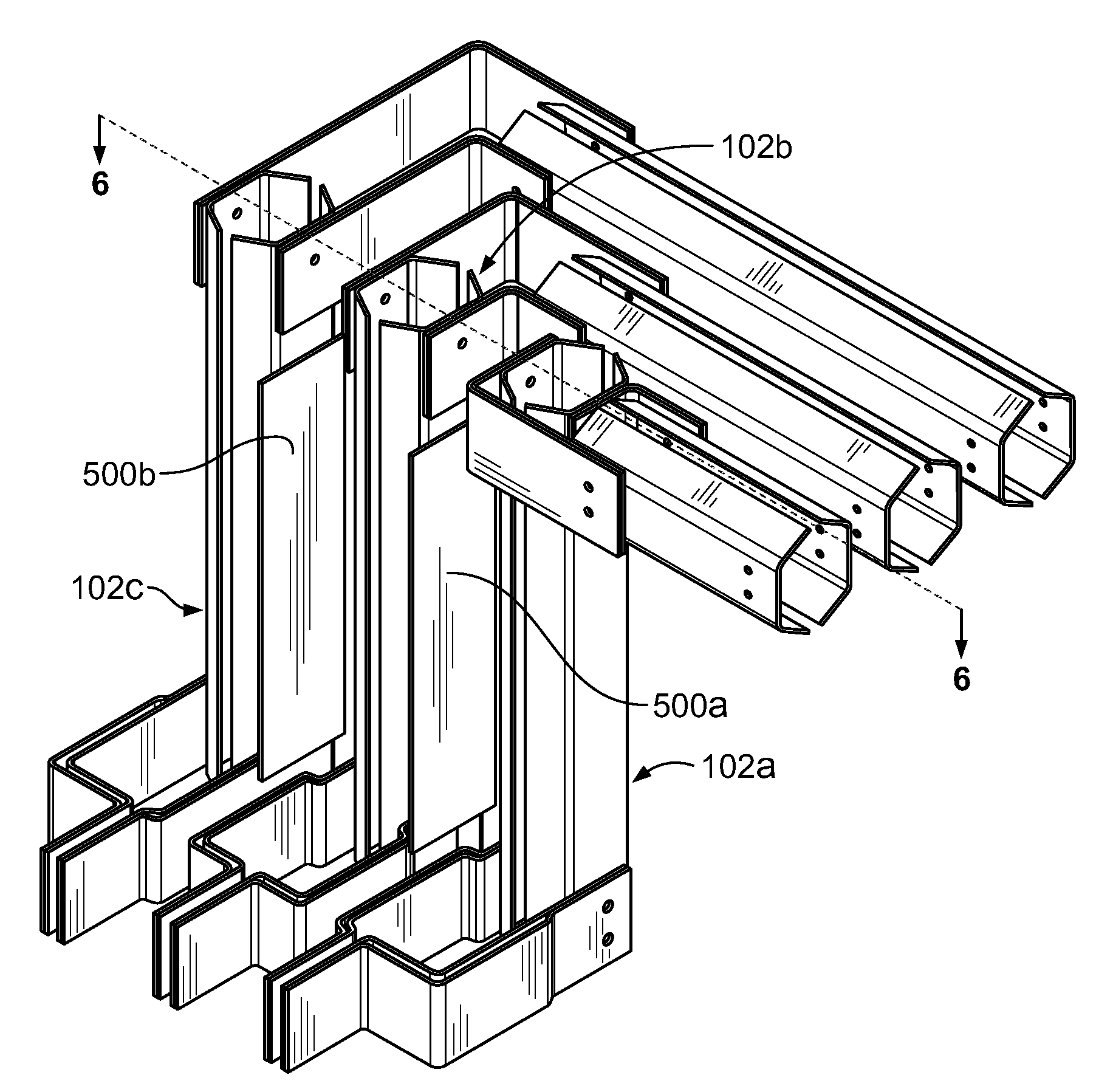
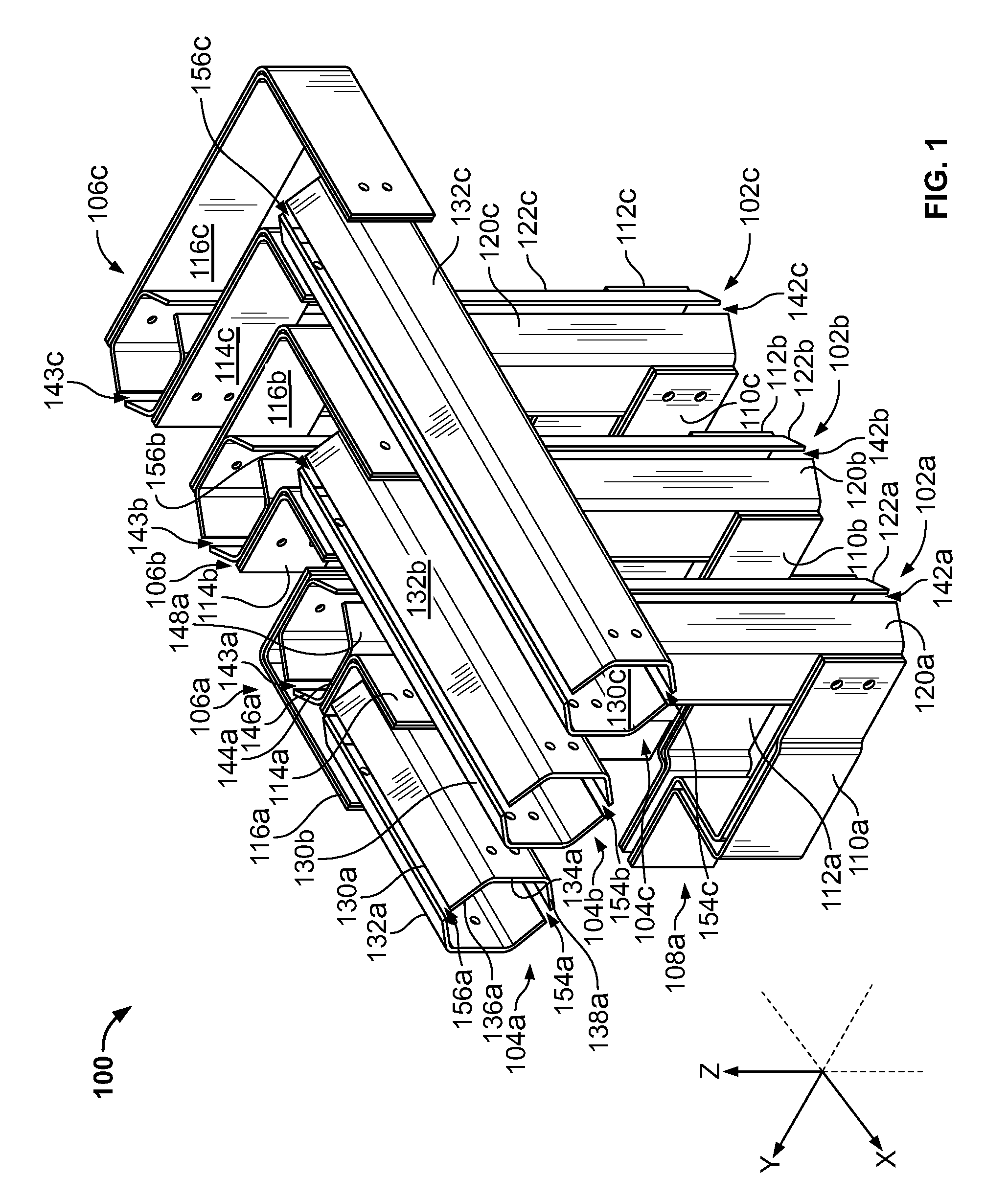
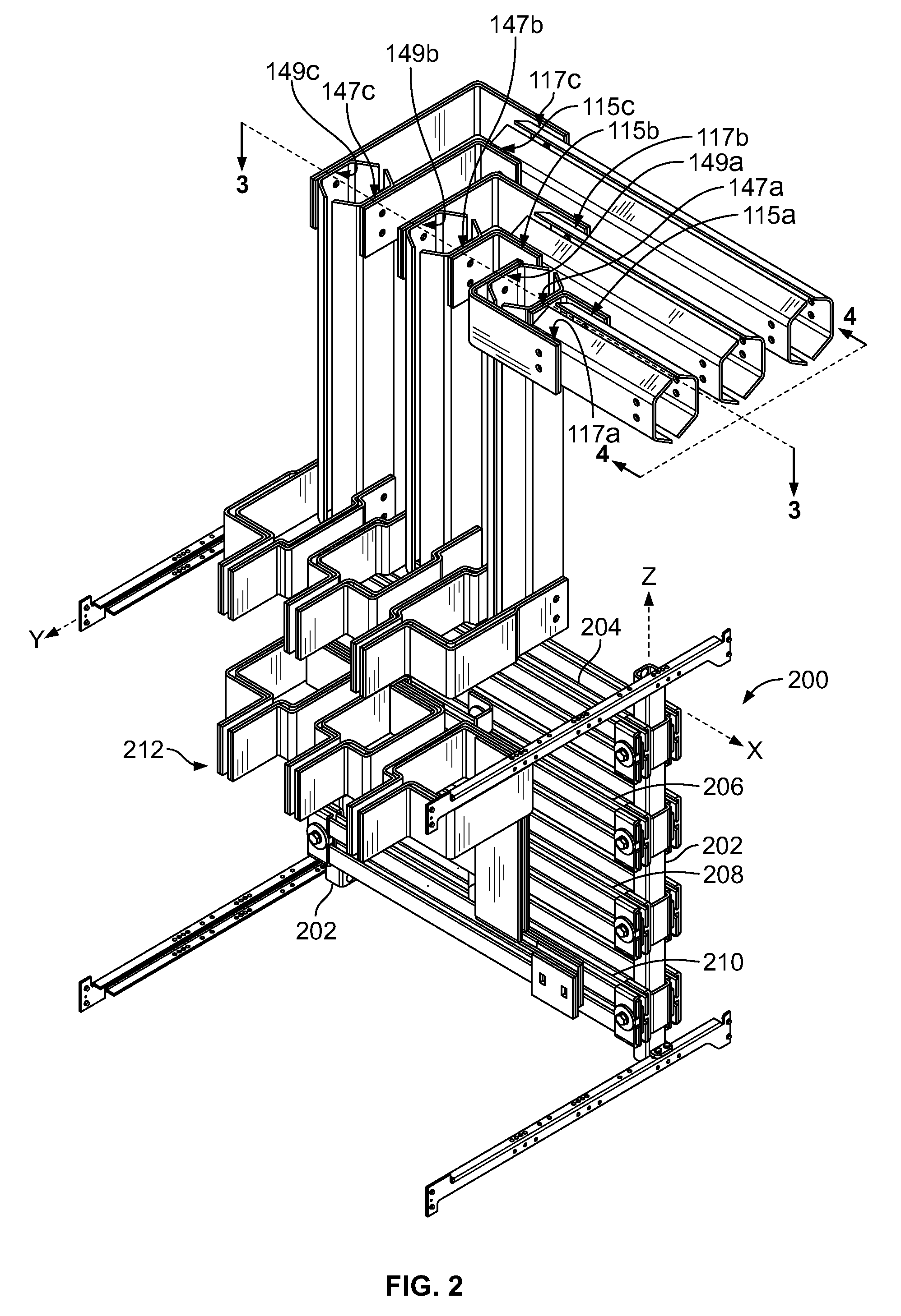
[0019]An isometric view of a bus system 100 for use in electrical distribution equipment such as switchgears, switchboards, and motor control centers, is shown in FIGS. 1 and 2. FIG. 2 shows the bus system 100 incorporated with a sub-assembly 200 for a cabinet of the electrical distribution equipment. The bus system 100 includes three vertical busbars or risers 102a,b,c, one for each phase of a polyphase alternating current distributed by the electrical distribution equipment (not shown). The top portions of the three vertical busbars 102a,b,c are electrically connected to ...


PUM


Abstract

A high ampacity busbar includes a pair of oppositely facing bowl-shaped conductors, each of whose cross sections resembles half of a hexagon or an open isosceles trapezoid, separated by an air gap in both horizontal and vertical configurations. The air gap increases cooling efficiency by natural convection by exposing more surface area of the conductors directly to the air flow within the electrical distribution equipment cabinet. As a result, the overall temperature of the bus system is reduced. The shaped conductors have smoother transitions presented to the electrical current between the bends of the conductors. These smooth transitions improve current distribution throughout the conductor, reducing skin effects. As a result of improved thermal dissipation and reduced skin effects, the amount of copper needed to maintain the same ampacity is significantly reduced. Magnetic shields can be placed between adjacent busbars, reducing proximity effects.

Description

FIELD OF THE INVENTION[0001]The present invention relates generally to bus systems, and in particular, to a bus system including efficient high-ampacity bowl-shaped tubular conductors.BACKGROUND OF THE INVENTION[0002]Electrical distribution equipment, including switchboards, switchgears, and motor control centers, use busbar conductors to connect circuit breakers and other protection equipment to loads. Conventionally, the busbar conductors include one or more vertical busbars, conventionally called “risers,” and one or more horizontal busbars. Existing busbar conductors include one or more flat conductors depending upon the desired current rating or ampacity of the distribution equipment. Other risers have an L-shape or U-shaped profile, but as the length of these conductors increases, the temperature of the surrounding air due to natural convection increases, resulting in poor thermal dissipation and current distribution. In the case of flat busbars, to counteract the adverse ther...

Claims


Application Information

Patent Timeline
Patent Type & Authority Applications(United States)
IPC IPC(8): H05K9/00H02G5/00
CPCH02B1/21H02G5/10H02B1/56
Inventor DIAZ, MAURICIO
Owner SQUARE D CO
Why Eureka
Try Eureka