Control of an electrical machine

a technology of electrical machines and control devices, which is applied in the direction of dynamo-electric machines, multiple motor speed/torque control, synchronous motor starters, etc., can solve the problems of uneven duty cycle of signals and adverse effects on the performance of electrical machines, and achieve the effect of improving power and/or efficiency of electrical machines, stable electrical machines, and reducing harmonics within current waveform drawn from ac power supply

Active Publication Date: 2012-04-05
DYSON TECH LTD
View PDF5 Cites 17 Cited by
  • Summary
  • Abstract
  • Description
  • Claims
  • Application Information

AI Technical Summary

Benefits of technology

[0005]By defining T_COM(2) as T_COM(1)+T_AVE−T_PD, the phase winding is commutated after the second edge by a period of time that takes into account duty-cycle imbalance in the period between the first and second edges. As a result, a more stable electrical machine is achieved. The power and / or efficiency of the electrical machine may therefore be improved. Additionally, if the electrical machine is powered by an AC power supply, the magnitude of harmonics within the current waveform drawn from the AC power supply may be reduced.
[0006]T_COM(1) may be proportional to T_AVE+T_PS, where T_PS is a phase-shift period. As a result, the method shifts commutation of the phase winding relative to each edge of the rotor-position signal by the phase-shift period. The phase-shift period may be negative so that commutation occurs before each edge, it may be zero so that commutation occurs in synchrony with each edge, or it may be positive so that commutation occurs after each edge. The method may comprise varying the phase-shift period, T_PS, in response to changes in the supply voltage used to excite the phase winding and / or the speed of the electrical machine. As a result, better control over acceleration, power, efficiency, and / or current harmonics may be achieved. T_COM(1) may be defined by additional parameters. For example, T_COM(1) may be corrected for armature reaction or for misalignment of the sensor that outputs the rotor-position signal.

Problems solved by technology

Tolerances within the electrical machine may mean that the duty cycle of the signal is not perfectly balanced.
As a result, the performance of the electrical machine may be adversely affected.

Method used


Image

  • Control of an electrical machine
  • Control of an electrical machine
  • Control of an electrical machine

Examples


Embodiment Construction

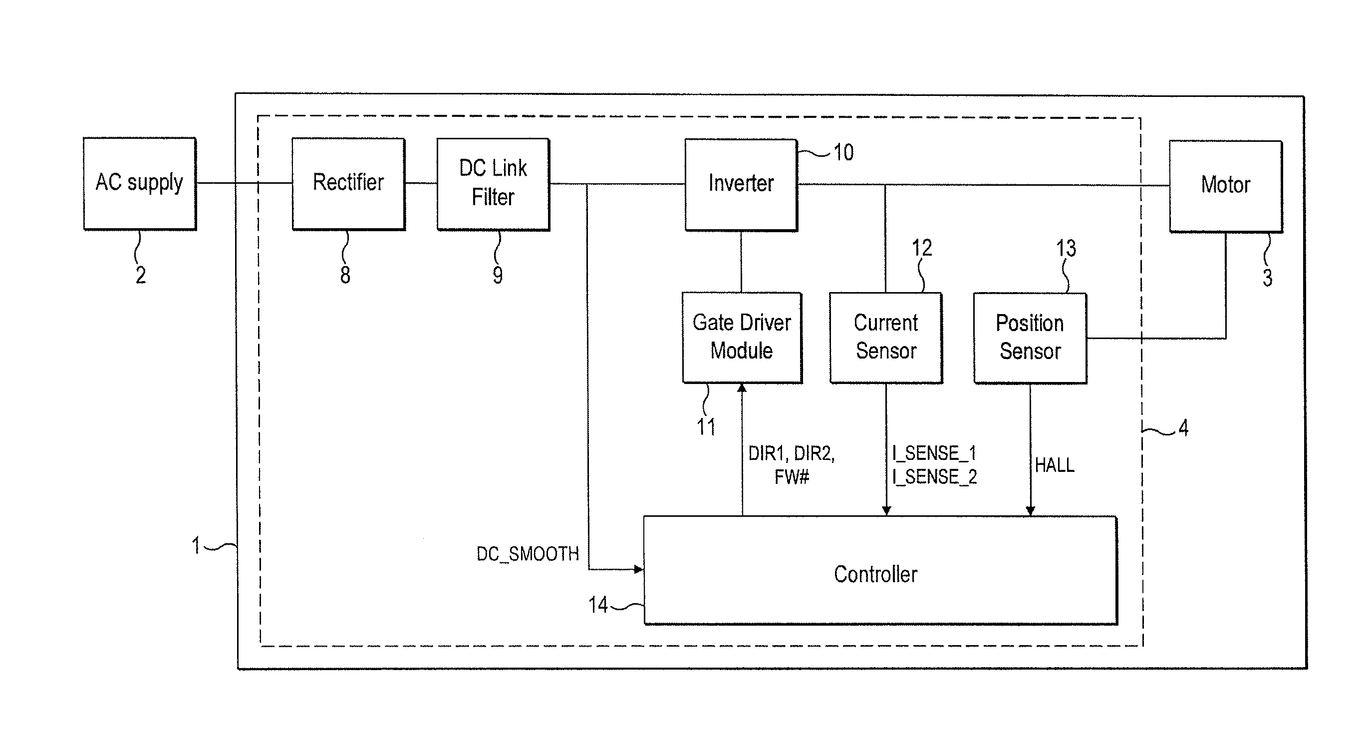
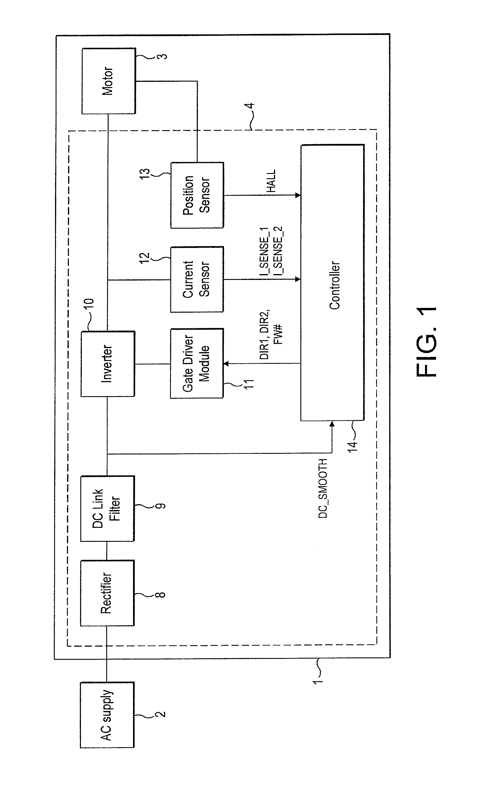
[0024]The motor system 1 of FIGS. 1 to 3 is powered by an AC power supply 2 and comprises a brushless motor 3 and a control system 4.

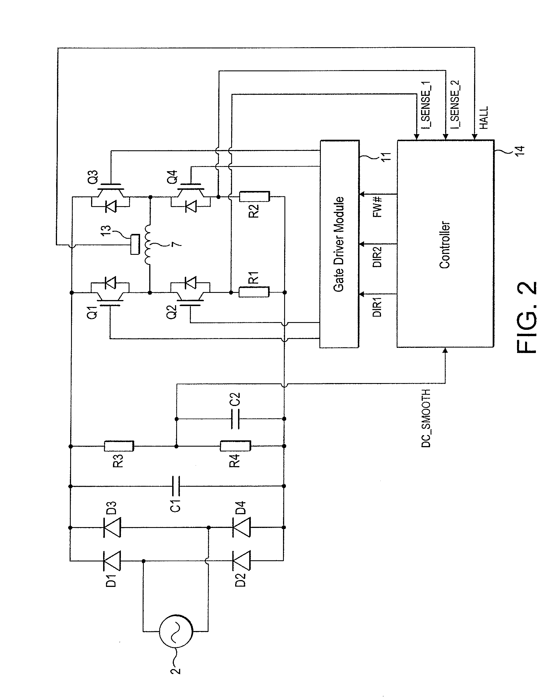
[0025]The motor 3 comprises a four-pole permanent-magnet rotor 5 that rotates relative to a stator 6. The stator 6 comprises a pair of c-shaped cores that define four stator poles. Conductive wires are wound about the cores and are coupled together to form a single phase winding 7.

[0026]The control system 4 comprises a rectifier 8, a DC link filter 9, an inverter 10, a gate driver module 11, a current sensor 12, a rotor-position sensor 13, and a controller 14.

[0027]The rectifier 8 comprises a full-wave bridge of four diodes D1-D4 that rectify the output of the AC power supply 2 to provide a DC voltage.

[0028]The DC link filter 9 comprises a capacitor C1 that smoothes the relatively high-frequency ripple that arises from switching of the inverter 10. If required, the DC link filter 9 may additionally smooth the rectified DC voltage at the fundamental fre...


PUM


Abstract

A method of controlling an electrical machine that includes commutating a phase winding of the electrical machine at a time T_COM(1) after a first edge and at a time T_COM(2) after a second edge of a rotor-position signal. T_COM(2) is defined by the equation: T_COM(2)=T_COM(1)+T_AVE−T_PD, where T_AVE is an average period between edges of the rotor-position signal, and T_PD is the period between the first and second edges. Additionally, a controller and control system that implement the method.

Description

REFERENCE TO RELATED APPLICATIONS[0001]This application claims the priorities of United Kingdom Application No. 1016739.3, filed Oct. 5, 2010, and United Kingdom Application No. 1017376.3, filed Oct. 14, 2010, the entire contents of which are incorporated herein by reference.FIELD OF THE INVENTION[0002]The present invention relates to control of an electrical machine.BACKGROUND OF THE INVENTION[0003]The performance of an electrical machine depends on accurate timing of phase excitation with rotor position. The electrical machine may include a sensor that outputs a signal indicative of the rotor position. Phase excitation then occurs at times relative to edges of the signal. Tolerances within the electrical machine may mean that the duty cycle of the signal is not perfectly balanced. As a result, the performance of the electrical machine may be adversely affected.SUMMARY OF THE INVENTION[0004]In a first aspect, the present invention provides a method of controlling an electrical mach...

Claims


Application Information

Patent Timeline
Patent Type & Authority Applications(United States)
IPC IPC(8): H02P6/16
CPCH02P6/002H02P6/008H02P6/142H02P6/16H02P25/04H02P6/147H02P25/023H02P6/15H02P6/157H02P6/26H02P6/28H02P25/03H02P6/34H02P6/182Y10S388/9281
Inventor DAI, HANPING
Owner DYSON TECH LTD
Why Eureka
Try Eureka