Bright field and dark field channels, used for automotive glass inspection systems

a technology of automotive glass inspection and dark field, applied in the direction of instruments, electrical equipment, geological measurements, etc., can solve the problems of reducing the signal-to-noise ratio (snr), reducing the detection capability for a broad variety of defects, and narrowing down the choice of effective solutions suitable, so as to overcome or mitigate one or more disadvantages of known glass inspection

Inactive Publication Date: 2010-03-04
SYNERGX TECH
View PDF5 Cites 36 Cited by
  • Summary
  • Abstract
  • Description
  • Claims
  • Application Information

AI Technical Summary

Benefits of technology

[0024]It is an object of the present invention to provide a glass inspection system that overcomes or mi...

Problems solved by technology

The requirement for simultaneous detection and identifying of a large variety of intrinsic float glass defects and manufacturing/processing defects has applied strong limitations on the design of inspection systems, narrowing down the choice of effective solutions suitable for the above-mentioned purpose.
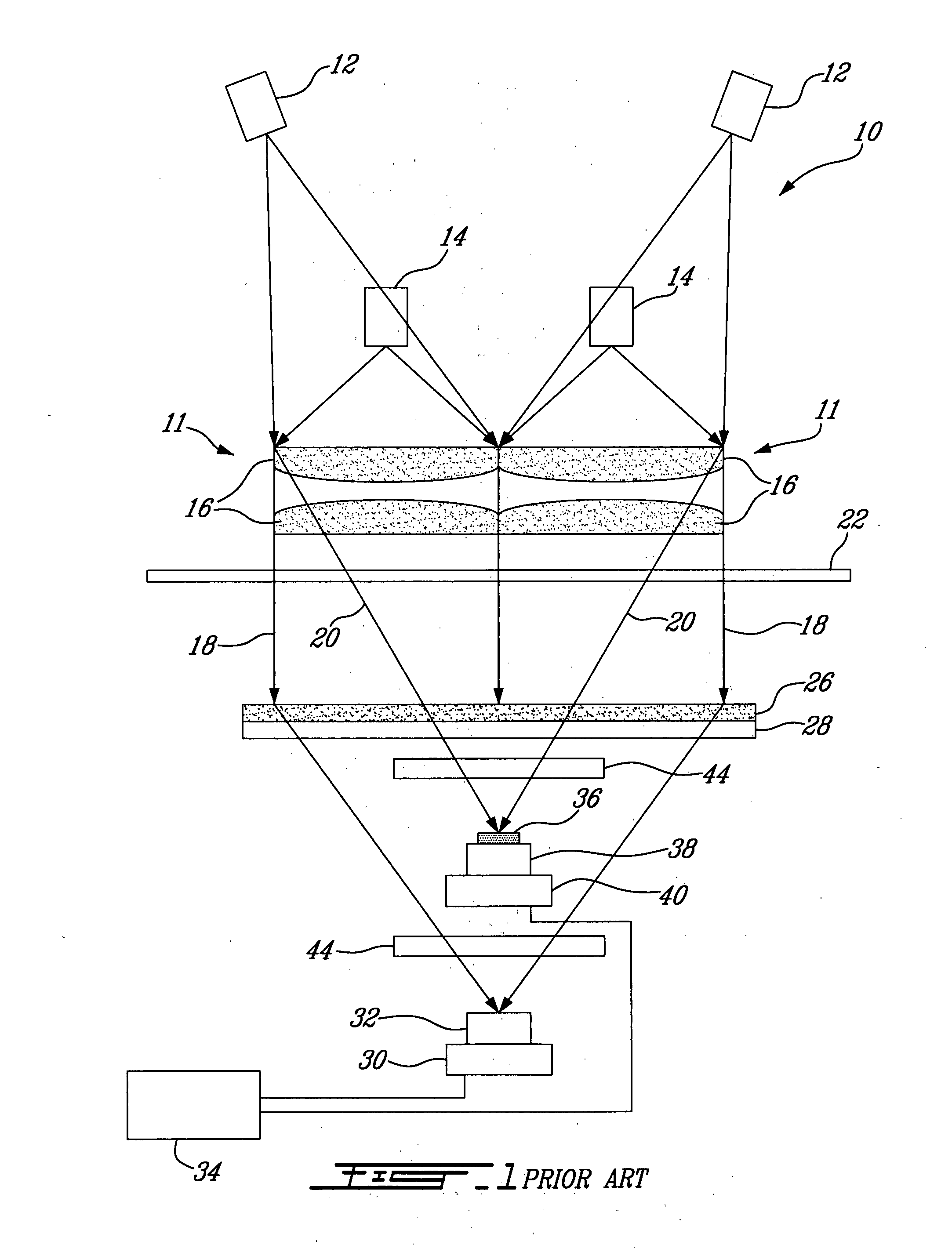
First, the use of lasers as light sources for the BF channels has shown that light intensity, passed through the glass samples, is modulated even in the absence of any glass defect. It manifests itself in a way that glass images, acquired with the BF channels, are disfigured with irregular strips of higher and lower light intensity. These intensity variations are known as “draw lines”. This effect has been observed for all glass samples inspected so far, with all glass inspection systems built in correspondence with the conventional art described above. The most pronounced “draw lines” magnitude observed reached 14% of the stationary BF illumination level for clear glass samples with an average light transmissivity of 90-92%. This modulation of the BF light intensity effectively decreases the signal-to-noise ratio (SNR) and degrades the detection capability for a broad variety of defects.
In addition, multiple cases were reported where the glass inspection system falsely reported as defective clear glass samples because the intensity of the BF light inside the glass reached the light intensity outside the glass sample.
After investigation, it was discovered that these false defect detections arise because laser light is coherent with a coherence length that is larger than the thickness of the inspected glass samples.
This limits the capability of the BF channel to detect both small defects and defects with low optical density, thereby severely degrading the optical performance of the BF channel.
Furthermore, it has been shown that the combination into one housing of the BF channel, DF channel and edge modules is problematic.
Indeed, the light generated by the edge modules and scattered by the glass sample edges, penetrates into the BF and DF cameras and creates overexposed BF and DF image fragments.
If the overexposed area is too large, the system fails to properly inspect it because of a l...

Method used


Image

  • Bright field and dark field channels, used for automotive glass inspection systems
  • Bright field and dark field channels, used for automotive glass inspection systems
  • Bright field and dark field channels, used for automotive glass inspection systems

Examples


Embodiment Construction

[0037]Techniques for the manufacture of glass are known. For example, glass may be converted to a molten state and then cast onto molten tin metal so that glass with a smooth surface may be obtained. Nonetheless, the glass that has been cast may be subject to a number of defects, including the presence of bubbles, dirt, stones, tin-drip distortion and other defects. Some such defects might arise from raw materials fed to the process while other defects will arise from processing problems, including incorrect temperature or other process parameters and aging of apparatus, especially of kilns or other apparatus used in the heating of the glass.

[0038]Subsequent to the casting of the glass, the glass is cut into sheets and then transferred to a manufacturer of glass articles for a particular end use. In the automobile industry, for instance, the glass articles could be windows of a vehicle, in which event the manufacturer will shape the glass to a particular size and configuration, grin...


PUM


Abstract

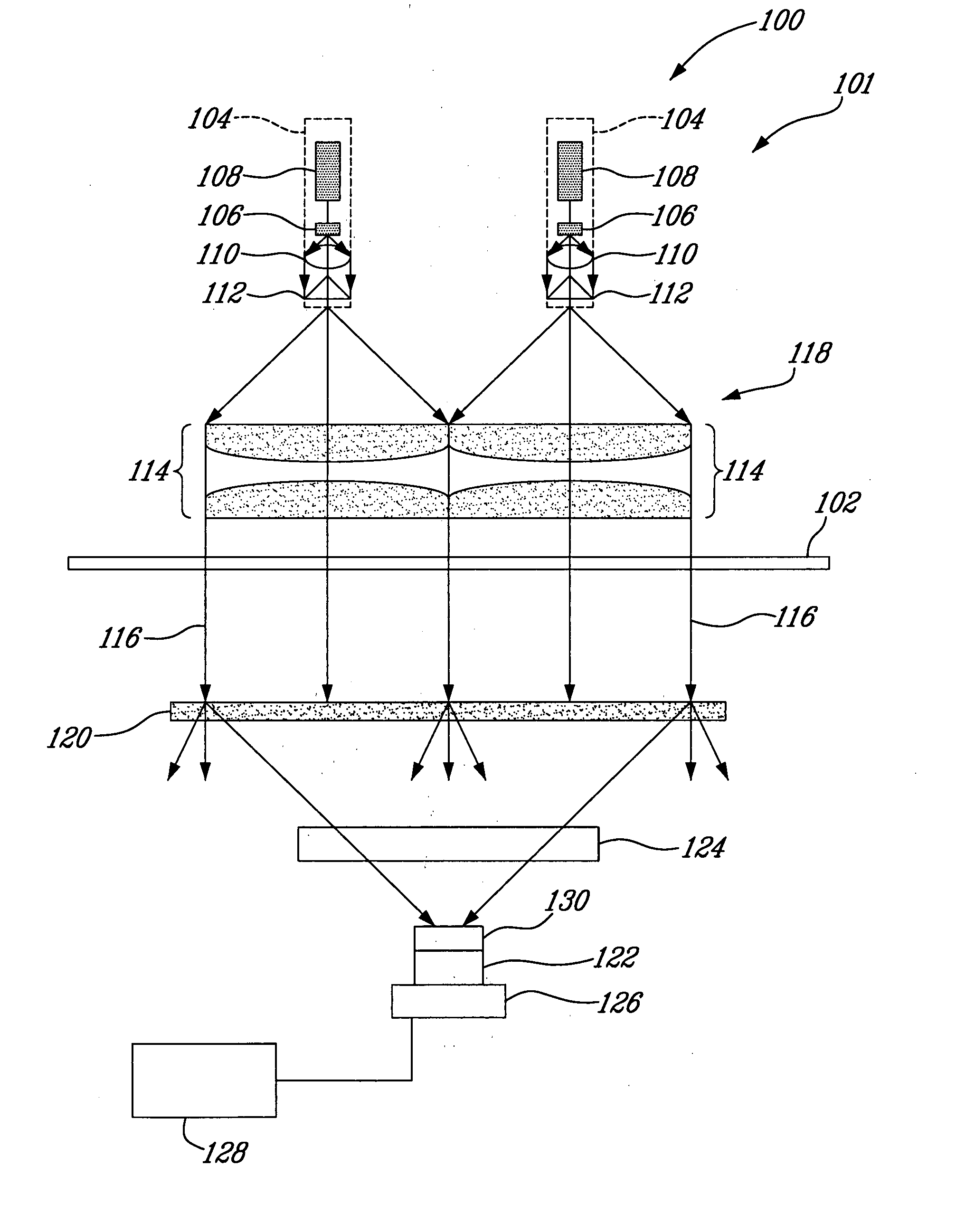
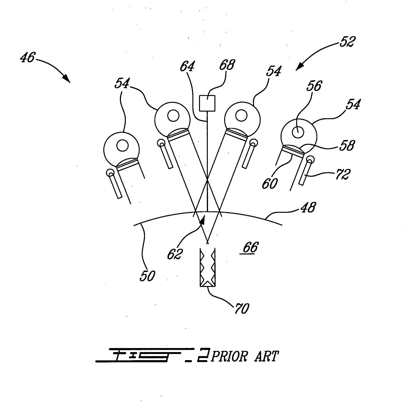
An inspection system for inspecting a sheet of glass comprises an illumination module, a collimating lens system, a telecentric imaging lens system and a Time Delay Integration line-scan camera. The illumination module has a low coherence light source emitting light. The collimating lens system has a focal point on the main axis thereof on which focal point its light source is located. The collimating lens system produces a collimated sheet of light from the emitted light. This collimated sheet of light passes through the sheet of glass. The telecentric imaging lens system concentrates the sheet of light passed through the sheet of glass on an image formation plane. The Time Delay Integration line-scan camera is positioned in a general area of the image formation plane. The camera is equipped with an antiblooming device. In another embodiment, an inspection system for inspecting a sheet of glass comprises a camera and a peripheral RDF illumination module. The camera is positioned on and points toward a first side of the sheet of glass. The peripheral RDF illumination module surrounds the camera and side, outside a field of view of the camera. The RDF illumination module is operative to illuminate the field of view with its RDF emitted light. The RDF illumination module is oriented so that the sheet of glass reflects the RDF emitted light away from the camera. The camera is positioned so as to be operative to receive the RDF emitted light if a RDF detectable defect is present on the sheet of glass and to avoid the RDF emitted light if no RDF detectable defect is present on the sheet of glass.

Description

FIELD OF THE INVENTION[0001]The present invention is related to the field of glass inspection systems. More particularly, the present invention is related to an automatic inspection system for the detection, identification and sizing of defects in curved or flat automotive sheets of glass.BACKGROUND OF THE INVENTION[0002]The automotive industry has quality standards that need to be respected when it comes to parts manufacturing. Because of high production rates, automating inspection of these manufactured parts is now necessary. Employing a number of physical principles, numerous efforts have been made through the years to develop systems that are suitable for the automated in-line inspection of automotive glass.[0003]The requirement for simultaneous detection and identifying of a large variety of intrinsic float glass defects and manufacturing / processing defects has applied strong limitations on the design of inspection systems, narrowing down the choice of effective solutions suit...

Claims


Application Information

Patent Timeline
IPC IPC(8): H01L31/14G01N21/896G01N21/958
CPCG01N21/896
Inventor LOPATIN, ALEKSEY
Owner SYNERGX TECH
Why Eureka
Try Eureka