Brushless high-frequency alternator and excitation method for dc, single-phase and multi-phase ac power-frequency generation

a high-frequency alternator, brushless technology, applied in the direction of windings, mechanical energy handling, electric generator control, etc., can solve the problems of increasing the size and complexity of the alternator device, heat loss and complexities of the rectification and high-frequency switching process of power electronics, and not allowing for variable speed operation to maximize fuel efficiency, etc., to minimize eddy current losses and low loss

Inactive Publication Date: 2010-03-04
RAVEN ENERGY ALTERNATIVES
View PDF8 Cites 28 Cited by
  • Summary
  • Abstract
  • Description
  • Claims
  • Application Information

AI Technical Summary

Benefits of technology

[0015]It is another object of the present invention to create an alternator incorporating three power-frequency phases within a single high-frequency alternator device that allows variable speed shaft operation while maintaining three-phase power-frequency output.
[0027]In the present invention, the magnetic pathways of the rotor and the stator are primarily radial and circumferential in nature, including a radial air gap between the rotor and the stator. The pathways are arranged to minimize any axial flow of the magnetic flux as such axial flow would contribute to eddy current losses. The magnetic pathways of the rotor and the stator are arranged so that the magnetic core structure may be made entirely of laminated electrical steel or laminated magnetic steel with low core loss in order to minimize eddy current losses and hysteresis losses.

Problems solved by technology

Furthermore, these approaches do not allow for variable speed operation to maximize the fuel efficiency of power sources such as internal combustion engines operating at partial load.
Disadvantages of this approach include the cost, efficiency penalties, heat loss and complexities of the rectification and high-frequency switching processes of the power electronics.
However, the axial magnetic flux flow of the latter device imposes the need for an axial return path for the magnetic flux, increasing the size and complexity of the alternator device.

Method used


Image

  • Brushless high-frequency alternator and excitation method for dc, single-phase and multi-phase ac power-frequency generation
  • Brushless high-frequency alternator and excitation method for dc, single-phase and multi-phase ac power-frequency generation
  • Brushless high-frequency alternator and excitation method for dc, single-phase and multi-phase ac power-frequency generation

Examples


Embodiment Construction

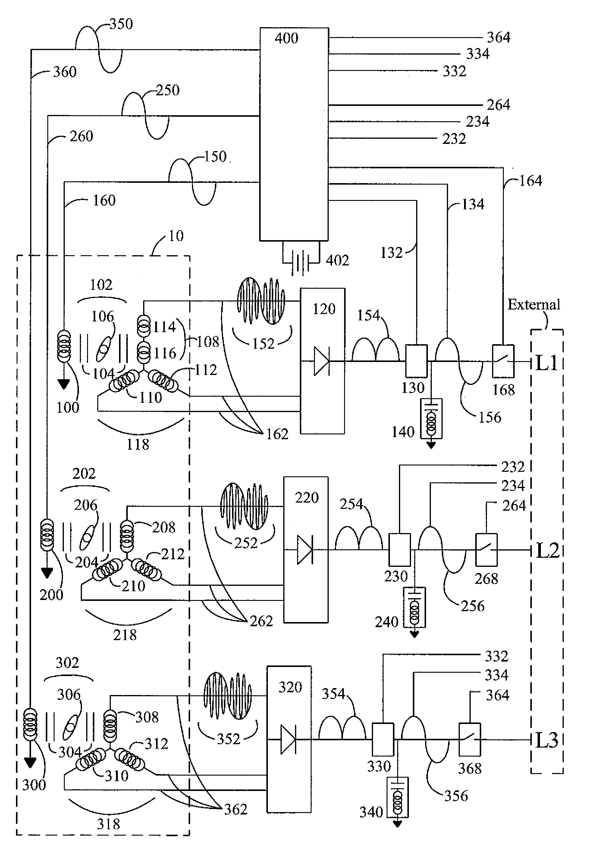
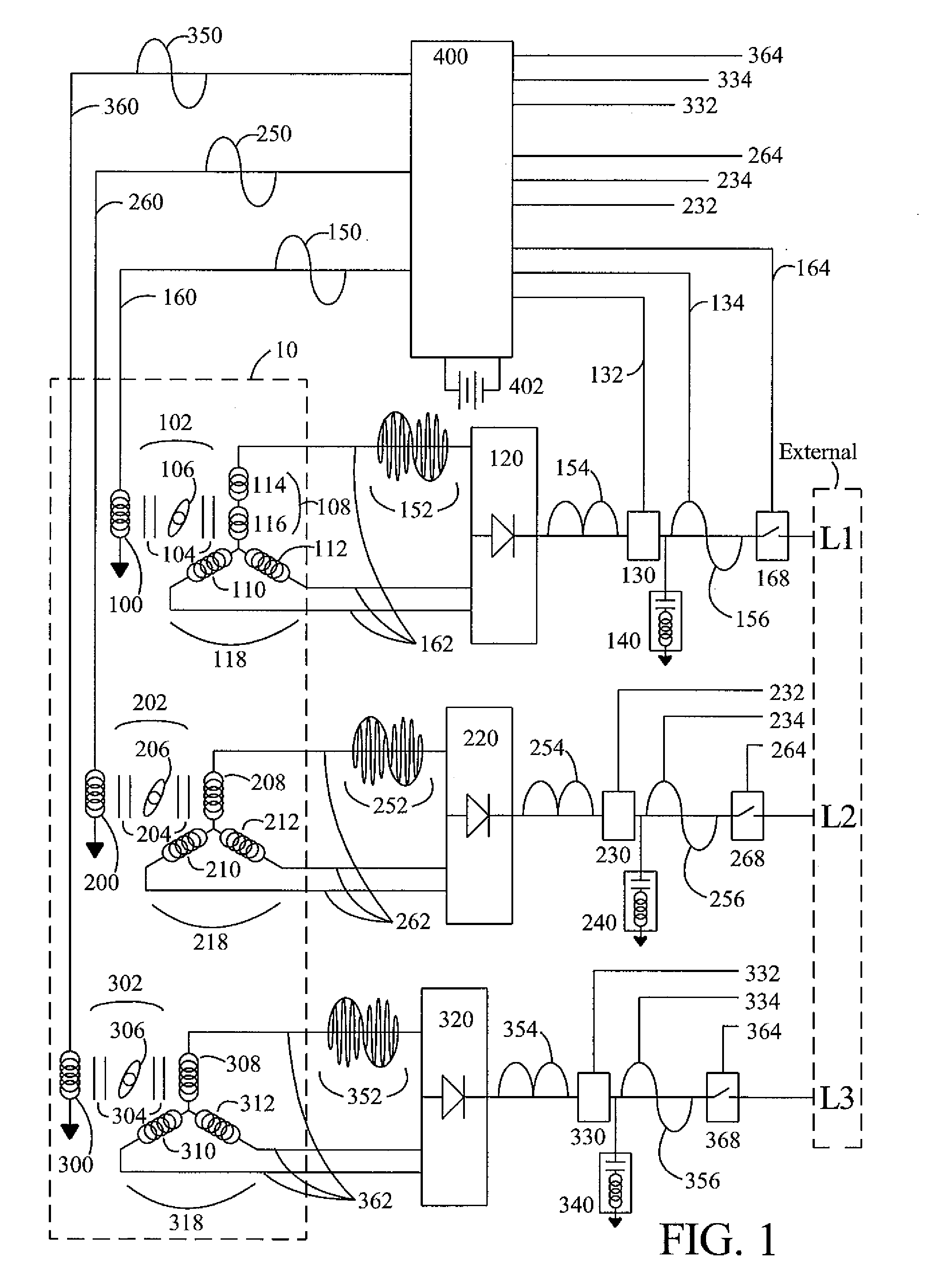
[0048]Referring to FIG. 1, a multi-stage high-frequency alternator 10 and excitation method for three-phase AC power-frequency generation of the present invention may be understood by first examining the general schematic arrangement of electrical connections and controls that couple it to a utility grid. For this preferred embodiment, FIG. 1 illustrates the arrangement for interconnection to an external three-phase fixed power-frequency grid in which equal line voltages L1, L2 and L3, are phase-separated from each other by one third of a power-frequency electrical cycle. It should be noted that this same configuration can be used for stand-alone applications, without grid connection, in which case L1, L2 and L3 represent respective three-phase external line loads.

[0049]The multi-stage high-frequency alternator 10 has a plurality of discrete field coil windings 100, 200 and 300 arranged so that electrical currents within each discrete field coil winding will excite magnetic flux wit...


PUM


Abstract

A method is disclosed for arranging and exciting the stator, rotor and various windings of a multi-stage brushless high frequency alternator so that the resulting multiple high frequency sub-phase armature winding outputs can be rectified and commutated into desired phases of power-frequency alternating current (AC) electrical output, including single-phase, split-phase, three-phase and other multiple phase output. Power frequency currents in field windings control output amplitude, output frequency, and output phase. If desired, DC power output can be accommodated as zero power-frequency operation. Devices incorporating this arrangement are suitable of generating fixed frequency electrical power while accommodating variable speed rotation of a generator shaft and offer multiple advantages over existing techniques. The capability to generate speed independent electric power allows natural power sources such as windmills and hydro-power stations to be efficiently coupled to fixed frequency power grids.

Description

CROSS REFERENCE TO RELATED APPLICATION[0001]This application is a continuation-in-part, and claims the priority benefit, of U.S. nonprovisional patent application Ser. No. 11 / 626,713, filed Jan. 24, 2007, entitled “Brushless High-Frequency Alternator and Excitation Method for Three-Phase AC Power-Frequency Generation” of the same named inventors and assigned to a common assignee. The content of that application is incorporated herein by reference.BACKGROUND OF THE INVENTION[0002]1. Field of the Invention[0003]This invention relates generally to high-frequency alternators used to generate electrical power, and more specifically to power-frequency generators suitable for use with variable shaft speed, and, more particularly, to three-phase power-frequency generators suitable for use with variable shaft speed.[0004]2. Description of the Prior Art[0005]Power-frequency electrical generation provides alternating current and voltage at power-frequencies common to utility “grid” networks, (...

Claims


Application Information

Patent Timeline
Patent Type & Authority Applications(United States)
IPC IPC(8): H02P9/14H02K3/28
CPCH02K7/1838H02P9/48H02P9/36H02K19/20
Inventor TUPPER, CHRISTOPHER N.WOOD, DUNCAN G.
Owner RAVEN ENERGY ALTERNATIVES
Why Eureka
Try Eureka