Band-gap reference voltage generator

Inactive Publication Date: 2010-03-04
ELECTRONICS & TELECOMM RES INST
View PDF8 Cites 24 Cited by
  • Summary
  • Abstract
  • Description
  • Claims
  • Application Information

AI Technical Summary

Benefits of technology

[0014]The CTAT voltage that is inversely proportional to absolute temperature is reduced by the threshold voltage VTH<sub2>—< / sub2>M5 of the fifth NMOS transistor. The band-gap reference voltage generator according to an exemplary embodiment of the present invention can reduce the weight α for the thermal voltage VT in order to set a sum of temperature coefficients to 0.

Problems solved by technology

However, a conventional band-gap reference voltage generator provides a reference voltage of about 1.25 V, it is not applicable to a circuit designed for applying a voltage lower than or equal to 1 V. There is a problem in that a power supply voltage of at least 1.5 V should be used to ensure smooth operation of transistors used in the reference voltage generator.
However, there is a problem in circuit design since only a core band-gap bias circuit within a chip needs an operation voltage of at least 1.5 V when a low supply voltage is used for a low-power design.
However, this band-gap reference voltage generator has a problem of increased circuit area since a relatively large-sized resistor is needed.

Method used


Image

  • Band-gap reference voltage generator
  • Band-gap reference voltage generator
  • Band-gap reference voltage generator

Examples


Embodiment Construction

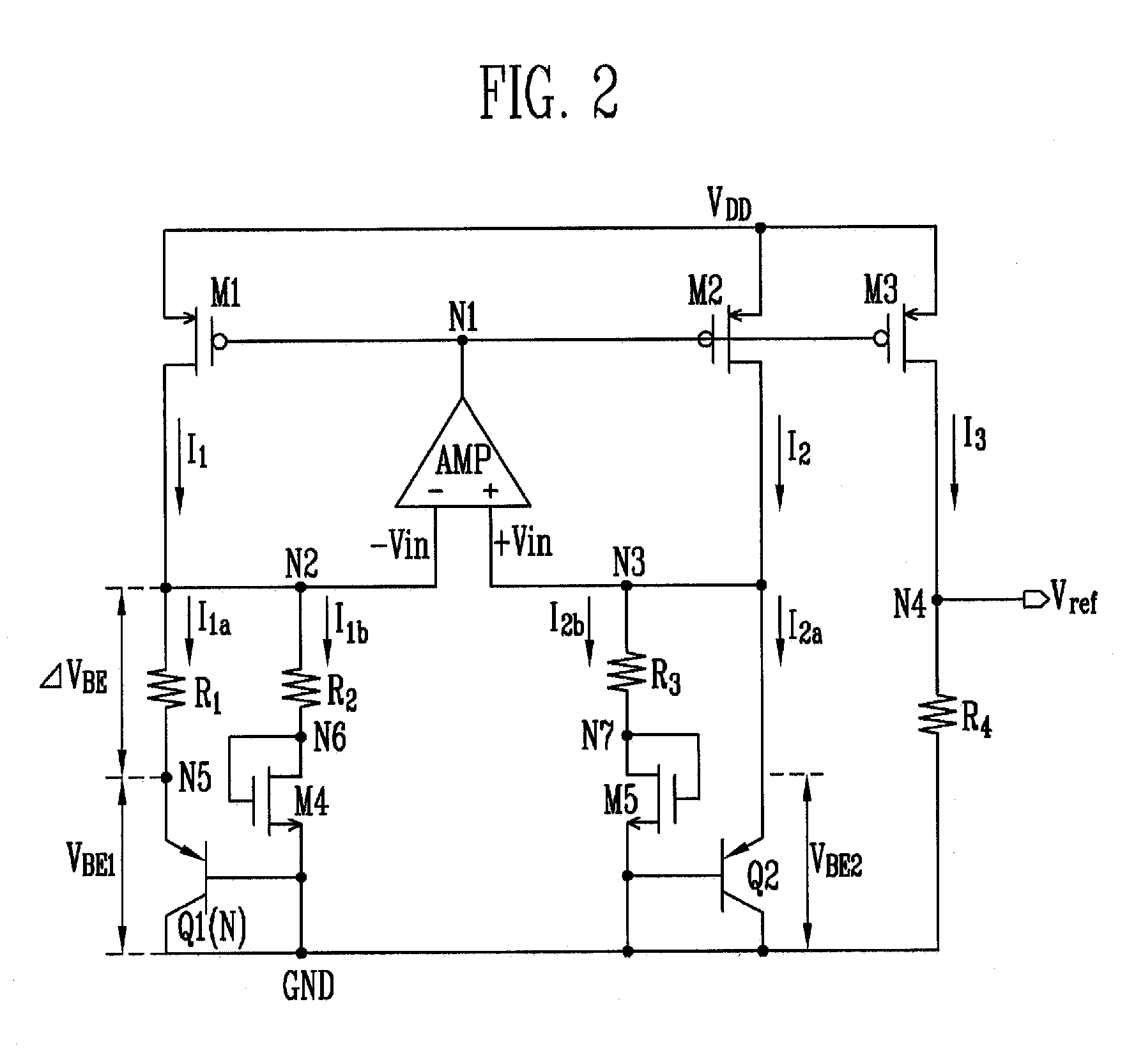
[0021]Hereinafter, exemplary embodiments of the present invention will be described with reference to the accompanying drawings. Although exemplary embodiments of the present invention have been disclosed for illustrative purposes, those skilled in the art will appreciate that various modifications, additions, and substitutions are possible, without departing from the scope of the present invention. Therefore, the present invention is not limited to the exemplary embodiments.

[0022]To inspect the main differences between the band-gap reference voltage generator according to an exemplary embodiment of the present invention and the conventional band-gap reference voltage generator, structure and operation of the conventional band-gap reference voltage generator will be described in detail.

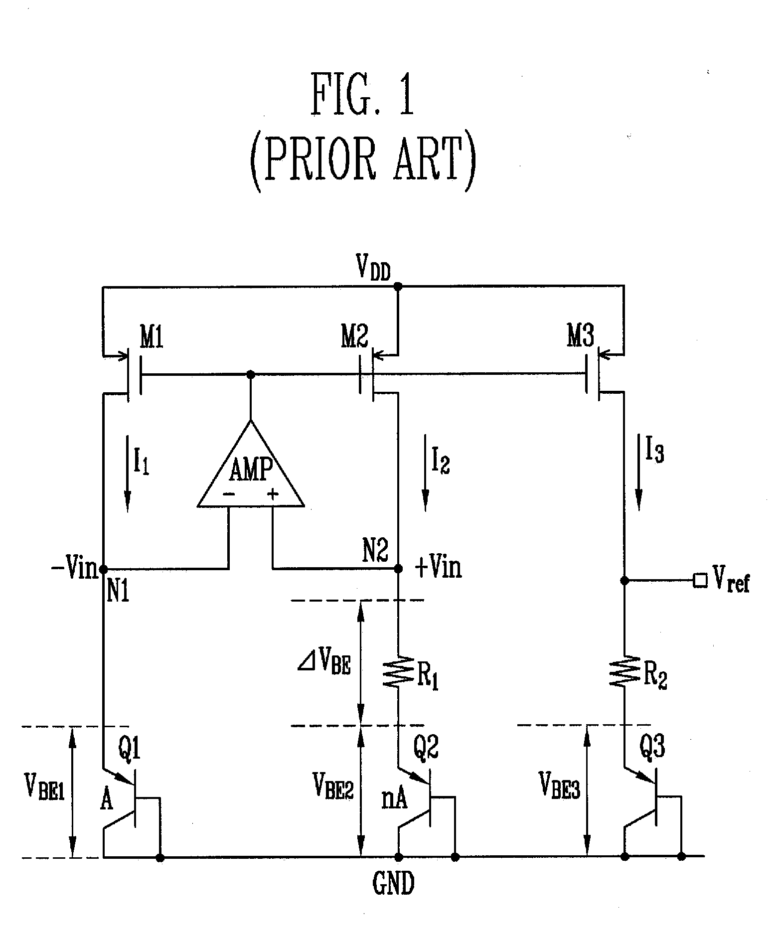
[0023]FIG. 1 is a circuit diagram illustrating a conventional complementary metal oxide semiconductor (CMOS) band-gap reference voltage generator.

[0024]Referring to FIG. 1, the conventional CMOS band-...


PUM


Abstract

A band-gap reference voltage generator is provided. N-channel metal oxide semiconductor (NMOS) transistors are respectively connected to bipolar transistors in parallel. A Complementary To Absolute Temperature (CTAT) voltage that is inversely proportional to absolute temperature is reduced by a threshold voltage of the NMOS transistor. A weight for a temperature coefficient of a Proportional To Absolute Temperature (PTAT) voltage that is directly proportional to absolute temperature is reduced and a resistance ratio for a temperature coefficient of 0 is reduced by about ½, thereby miniaturizing the band-gap reference voltage generator. A reference voltage lower than or equal to 1 V can be provided by resistors respectively connected to the bipolar transistors in parallel.

Description

CROSS-REFERENCE TO RELATED APPLICATION[0001]This application claims priority to and the benefit of Korean Patent Application No. 10-2008-0085999, filed Sep. 1, 2008, the disclosure of which is incorporated herein by reference in its entirety.BACKGROUND[0002]1. Field of the Invention[0003]The present invention relates to a band-gap reference voltage generator, and more particularly, to a band-gap reference voltage generator that can be miniaturized by reducing a size of a resistor occupying a large chip area and can provide a stable reference voltage lower than or equal to 1 V.[0004]2. Discussion of Related Art[0005]In general, all analog / radio frequency (RF) circuits or digital circuits manufactured with chips need a stable and accurate bias voltage for efficient operation. Therefore, a band-gap reference voltage generator is used to provide a stable reference voltage regardless of temperature variation.[0006]However, a conventional band-gap reference voltage generator provides a re...

Claims


Application Information

Patent Timeline
IPC IPC(8): G05F3/16
CPCG05F3/30G05F3/24
Inventor CHO, YOUNG KYUNJEON, YOUNG DEUKNAM, JAE WONKWON, JONG KEE
Owner ELECTRONICS & TELECOMM RES INST
Why Eureka
Try Eureka