Biosensor with evanescent waveguide and integrated sensor

a biosensor and waveguide technology, applied in the field of evanescent field based sensor systems, can solve the problems of more accurate and complex, further drawbacks, and inability to meet the needs of users,

Inactive Publication Date: 2010-03-04
KONINKLIJKE PHILIPS ELECTRONICS NV
View PDF9 Cites 54 Cited by
  • Summary
  • Abstract
  • Description
  • Claims
  • Application Information

AI Technical Summary

Benefits of technology

[0096]In the simplest case of the competitive assay, the sample which contains the analyte in unknown concentration as well as a known amount of a compound that is similar except for luminescent labelling is brought in to contact with the surface of the evanescent field induced sensor system according to the present invention, where the luminescent labelled and unlabelled molecules compete for the binding sites at their immobilised detector substances. A maximum luminescence signal is achieved in this assay configuration when the sample contains no analyte. With increasing concentration of the substance to be detected, the luminescence signals under observation become lower.
[0097]In a competitive immunoassay it does not necessarily have to be the antibody, which is immobilised: the antigen too can be immobilised on the surface of the evanescent field induced sensor system according to the present invention as detector substance. Usually it is immaterial which of the partners is immobilised in chemical or biochemical affinity assays. This is a basic advantage of luminescence-based assays over methods such as surface Plasmon resonance or interferometry, which are based on the change in adsorbed mass in the evanescent field of the waveguide layer.

Problems solved by technology

Further, the quite small nanowells requires a more accurate and still more complex positioning of the bound molecules in all the wells, which leads to a further drawback.
Further, said prior art evanescent field waveguide biosensor has no integrated filter sandwiched between the waveguide layer and the sensor.

Method used


Image

  • Biosensor with evanescent waveguide and integrated sensor
  • Biosensor with evanescent waveguide and integrated sensor
  • Biosensor with evanescent waveguide and integrated sensor

Examples


Embodiment Construction

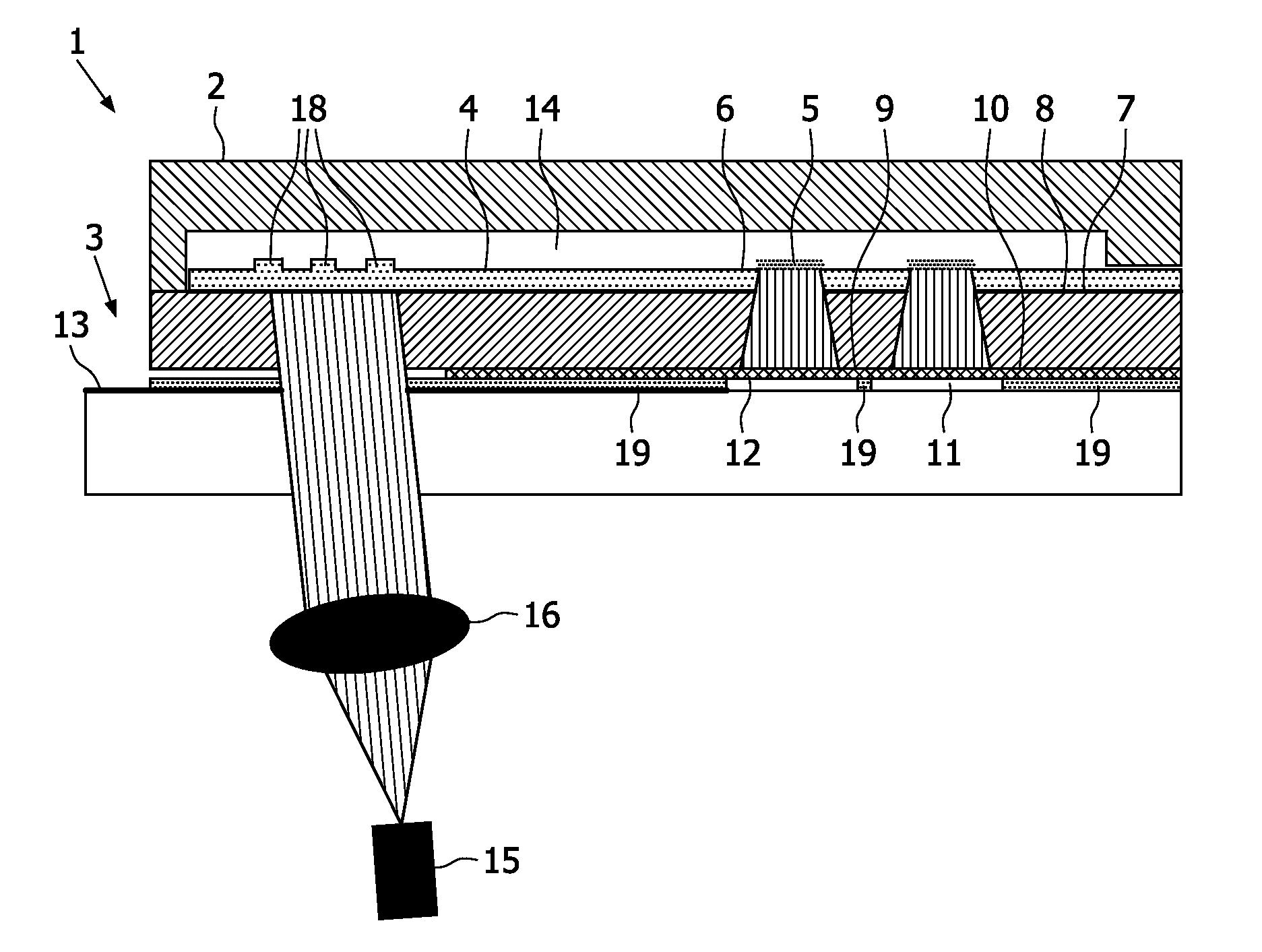
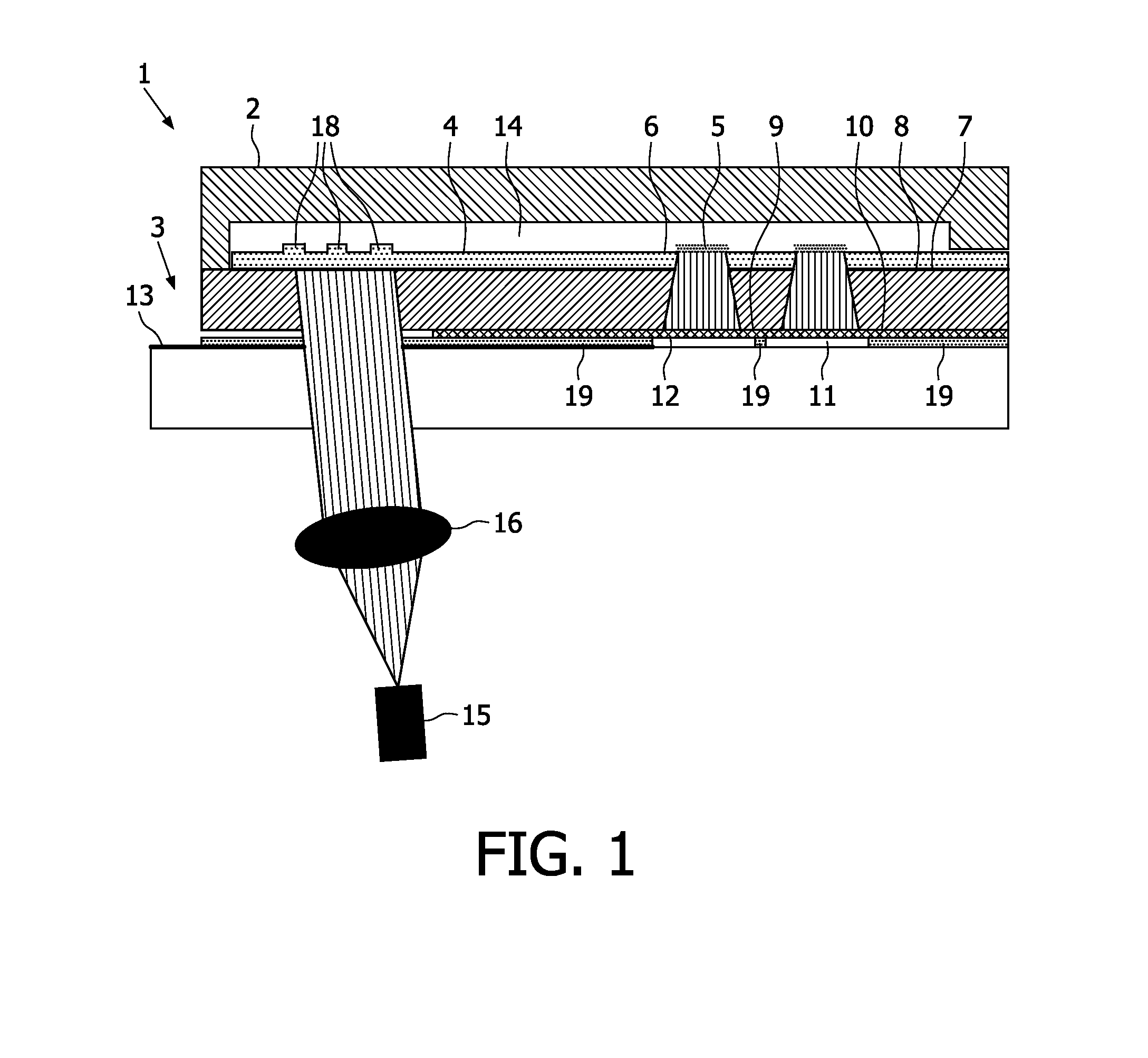
[0121]FIG. 1 shows an evanescent field induced sensor system 1 useful in diagnostic applications with an housing 2. The housing 2 is arranged on top of an integrated waveguide sensor 3. The integrated waveguide sensor 3 comprises a polymer waveguide layer 4 of polyethersulfone (PES) with a thickness of 250 nm and a refractive index of n2=1.65 on a cladding layer 7 of polymethylmethacrylate (PMMA) with a thickness of 1 mm and a refractive index of n3=1.49. On top of the upper outer surface 6 of the polymer waveguide layer 4 capture compounds 5 are arranged to detect a specific chemical substance. On the upper outer surface of the polymer waveguide layer 4 a grating structure of a plurality of recesses 18 for enhancing the coupling of the light wave into said transparent polymer waveguide are arranged. Alternatively, the grating structure can also be present at the interface between the cladding layer and the wave guiding layer. Between the upper outer surface of the polymer waveguide...


PUM

PropertyMeasurementUnit
refractive indexaaaaaaaaaa
thicknessaaaaaaaaaa
thicknessaaaaaaaaaa

Abstract

The present invention is directed to a waveguide sensor as well as to an evanescent field induced evanescent field induced sensor system for use in diagnostic housing and an integrated waveguide sensor comprising: a waveguide layer,—capture compounds applied on the upper surface of said waveguide layer for 5 specific bonding to target substances,—a cladding layer surface of said waveguide layer,—a filter which is transmitting for luminescent radiation while absorbs and/or reflects radiation of excitation radiation, wherein the filter is arranged below the lower 10 surface of said cladding layer, at least one detector for sensing luminescent radiation, wherein the detector is arranged below the lower surface of said filter, a substrate that is connected with the detector and comprises the electrical interface of said detector; wherein 15 between the upper surface of the waveguide layer and along at least a lower surface section of the housing a channel is formed for receiving a fluidic probe; and the luminescent radiation is generated by luminescent tag bound to target substances as a result of their excitation by the evanescent field. This provides an improved sensitivity of the evanescent field induced sensor 20 system.

Description

FIELD OF THE INVENTION[0001]This invention relates to an evanescent field based sensor system. More specifically, the invention relates to a sensor system with evanescent waveguide and integrated detector for use as a chemical or biosensor of detecting biological molecules.BACKGROUND OF THE INVENTION[0002]Evanescent luminescence excitation is of great interest in the analytical field, as the excitation is limited to the direct environment of the wave guiding layer. In particular, evanescent field excited fluorescence is a very important technology for biosensors because of its unique sensitivity.[0003]A significant advantage of detecting bound fluorescent molecules that are excited using an evanescent wave is that the emitted fluorescent light can be detected outside the aqueous reaction solution. Most complex biological solutions contain molecules that interfere with fluorescent emission. This means that when a fluorescent molecule is excited it emits a photon and rather than being...

Claims


Application Information

Patent Timeline
Patent Type & Authority Applications(United States)
IPC IPC(8): C12Q1/00G01N21/64G01N33/24G01N33/18
CPCG01N21/6454G01N21/7703G01N21/648
Inventor WIMBERGER-FRIEDL, REINHOLDYOUNG, NIGEL DAVIDVAN DER ZAAT, PIETER JAN
Owner KONINKLIJKE PHILIPS ELECTRONICS NV
Why Eureka
Try Eureka