System and method for controlling ramp rate of solar photovoltaic system

a solar photovoltaic and system technology, applied in non-electric variable control, process and machine control, instruments, etc., can solve the problems of slow rate, difficult to change the power output of thermal power generators quickly enough, and ramping down of thermal power generators

Active Publication Date: 2010-03-04
GENERAL ELECTRIC CO
View PDF14 Cites 182 Cited by
  • Summary
  • Abstract
  • Description
  • Claims
  • Application Information

AI Technical Summary

Benefits of technology

[0007]Briefly, in accordance with one embodiment of the invention, a solar photovoltaic (PV) control system comprises:

Problems solved by technology

However, it is often difficult to change power output of thermal power plants quickly enough.
Ramping down of such thermal power generators may require even slower rates to minimize risk of damaging plant components.
However this limits the capture of solar energy and increases the effective cost of energy of the PV system(s).
Further, although power ramp rate control has been achieved to some degree by such techniques on individual generators and wind farms, the problem has not been addressed at a photovoltaic system level.

Method used


Image

  • System and method for controlling ramp rate of solar photovoltaic system
  • System and method for controlling ramp rate of solar photovoltaic system
  • System and method for controlling ramp rate of solar photovoltaic system

Examples


Embodiment Construction

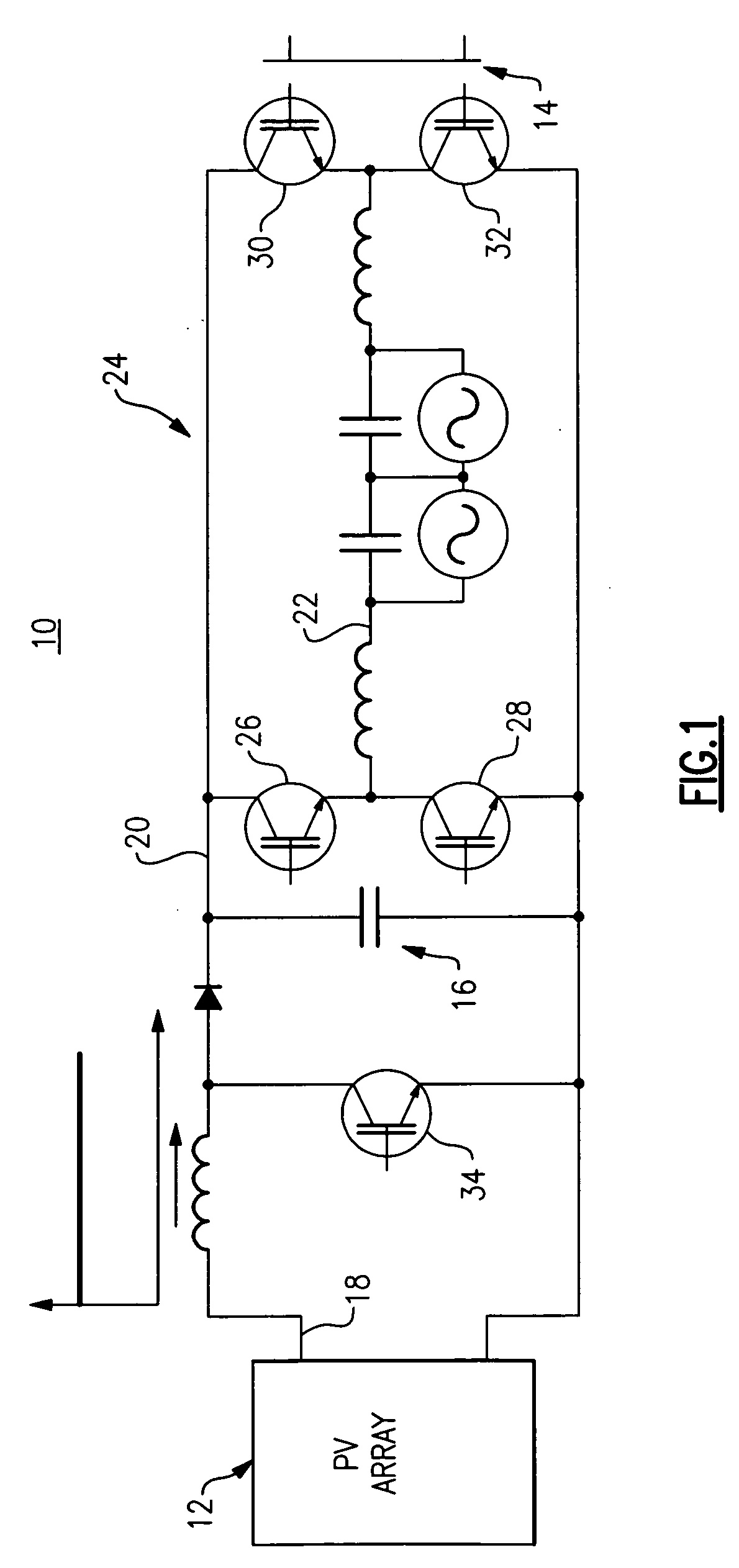
[0030]FIG. 1 is illustrates a photovoltaic inverter 10 topology that is known in the art. Photovoltaic inverter 10 employs a two-stage power circuit to convert a varying DC voltage of a PV array 12 to a fixed frequency AC current for a power grid 14. Photovoltaic inverter 10 uses a DC link capacitor 16 to implement the intermediate energy storage step. This means the PV inverter 10 first converts the variable PV DC voltage 18 to a constant DC voltage 20 that is greater than the grid voltage via a boost converter, and subsequently converts the constant DC voltage 20 to a current 22 via a PWM circuit 24 that can then be injected into the grid 14. Photovoltaic inverter 10 topology employs five switching devices 26, 28, 30, 32, 34 that are all switching at a high frequency.

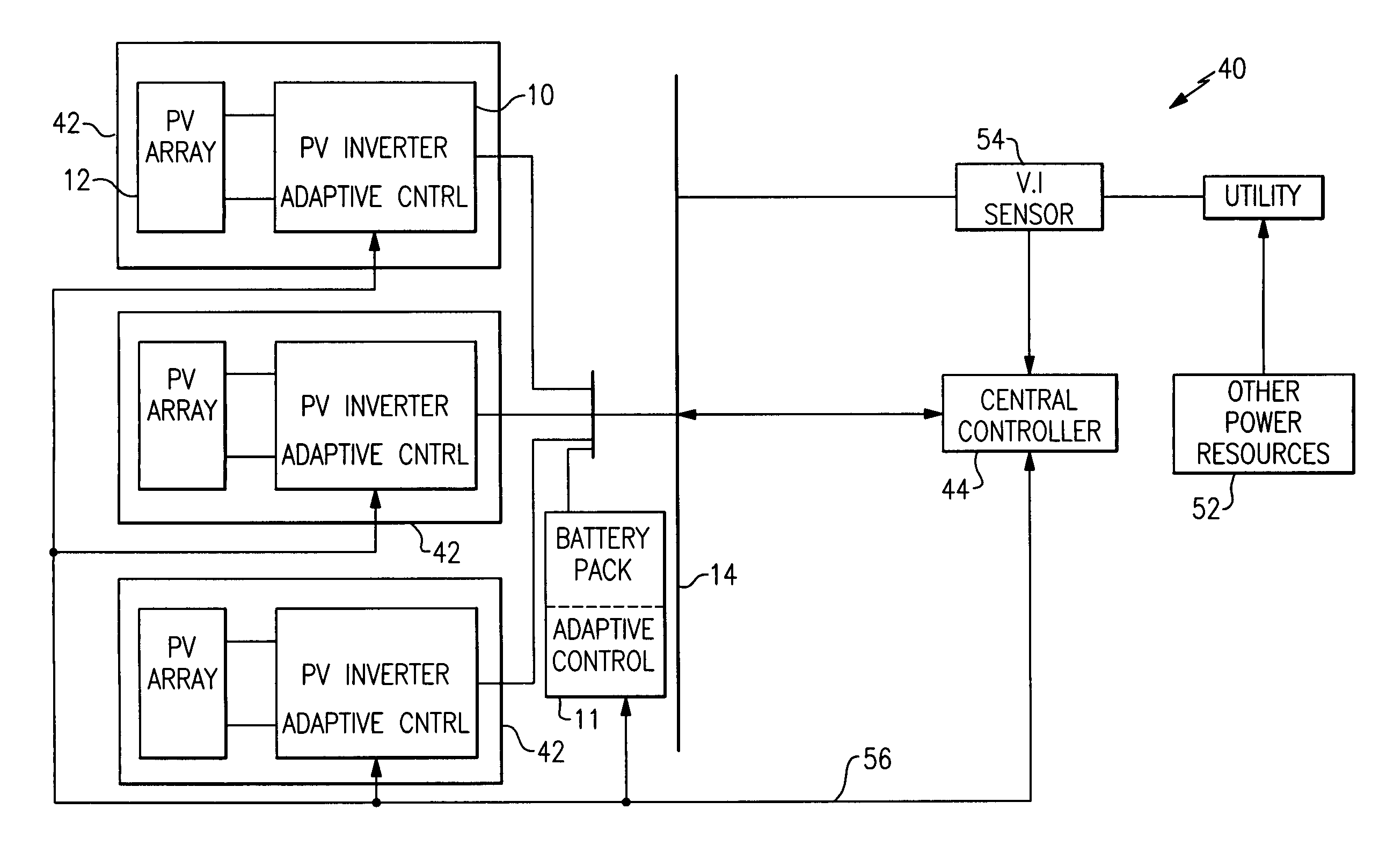
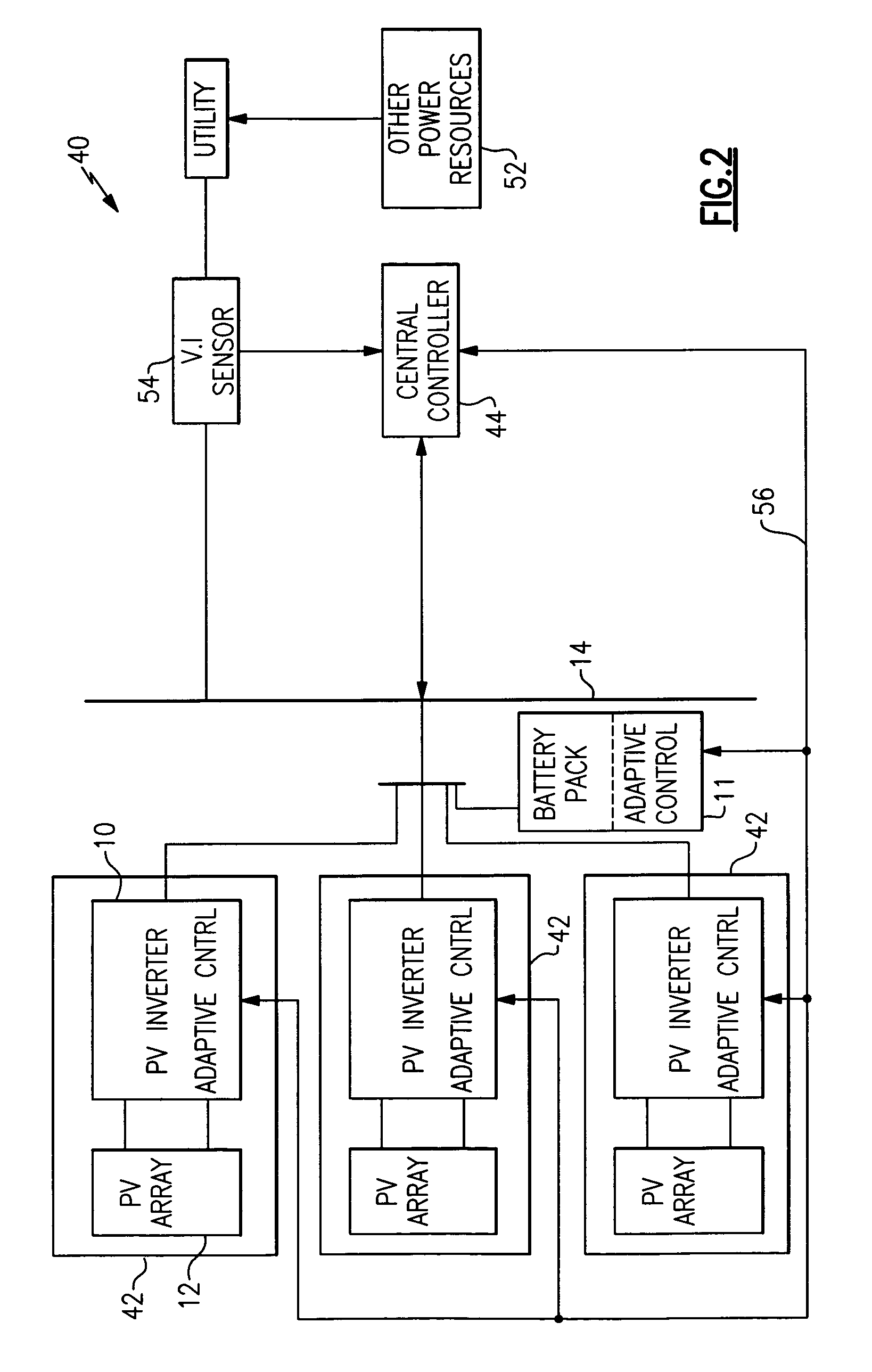
[0031]A system and method for controlling collective power ramp rate of a PV system having a plurality of PV subsystems / inverters via a central or supervisory PV system controller are described below for particular em...


PUM


Abstract

A photovoltaic (PV) control system generates a power output rate control signal based on a monitored rate of change of collective power output generated via a plurality of PV subsystems and a desired collective output power change rate for the plurality of PV subsystems and communicates the power output rate control signal to the plurality of PV subsystems to control a rate of change of one or more operating parameters of individual PV subsystems in order to control a rate of change of collective output power of the plurality of solar PV subsystems.

Description

BACKGROUND[0001]The invention relates generally to photovoltaic (PV) power generation, and more particularly to techniques for controlling power ramp rates of single or multiple PV systems / inverters associated with single or multiple PV arrays.[0002]Photovoltaic cells generate direct current (DC) power with the level of DC current being dependent on solar irradiation and the level of DC voltage dependent on temperature. When alternating current (AC) power is desired, an inverter is used to convert the DC energy into AC energy. Typical PV inverters employ two stages for power processing with the first stage configured for providing a constant DC voltage and the second stage configured for converting the constant DC voltage to AC current. Often, the first stage includes a boost converter, and the second stage includes a single-phase or three-phase inverter system.[0003]Single and three phase photovoltaic inverters generally require a two-stage conversion power circuit to convert the v...

Claims


Application Information

Patent Timeline
Patent Type & Authority Applications(United States)
IPC IPC(8): H02J3/46H01L31/042
CPCY02E10/58H02J3/18H02J3/385Y02E10/50Y10S323/906Y02E10/56H02J2300/26H02J3/381H02J2300/24H02J3/48
Inventor LIU, YANGARCES, LUIS JOSEBOSE, SUMIT
Owner GENERAL ELECTRIC CO
Why Eureka
Try Eureka