
Exterior Airbag Deployment Techniques

a technology of external airbags and deployment techniques, applied in the direction of reradiation, pedestrian/occupant safety arrangement, instruments, etc., can solve the problems of inability to compensate for vehicle pitch or ground elevation change, all prior art systems will suffer from this inaccuracy, and visibility is unacceptabl

Inactive Publication Date: 2010-03-04
AMERICAN VEHICULAR SCI
View PDF47 Cites 37 Cited by
  • Summary
  • Abstract
  • Description
  • Claims
  • Application Information

AI Technical Summary

Benefits of technology

"The present invention provides an improved airbag module with an anticipatory sensor system that can deploy external airbags based on data received by the sensor system. The sensor system uses a source of radiant energy and pattern recognition systems to assess the probable severity of an impact and initiate inflation of the airbag(s) accordingly. The airbag module can be mounted at various locations on the vehicle, such as the side, door, front, or rear, and can be designed to protect both occupants and pedestrians in the event of a crash. The anticipatory sensor system can also adjust the pressure in the airbag based on the information about the impact to optimize its performance."

Problems solved by technology

No attempt is made to compensate for vehicle pitch or for changes in ground elevation.
Since this angle is a critical factor in the Doppler velocity equation, all prior art systems will suffer from this inaccuracy.
Nevertheless, the inventions herein can contribute to safe driving in these conditions, if such driving is attempted, since an indication will be obtained by the system based on the elliptical reflections from the laser diode indicating that the visibility is unacceptable.
“Out-of-position” as used for an occupant will generally mean that the occupant, either the driver or a passenger, is sufficiently close to an occupant protection apparatus (airbag) prior to deployment that he or she is likely to be more seriously injured by the deployment event itself than by the accident.
It may also mean that the occupant is not positioned appropriately in order to attain the beneficial, restraining effects of the deployment of the airbag.
Thus, the state of the vehicle could be normal when the vehicle is operating properly on a highway or abnormal when, for example, the vehicle is experiencing excessive angular inclination (e.g., two wheels are off the ground and the vehicle is about to rollover), the vehicle is experiencing a crash, the vehicle is skidding, and other similar situations.

Method used


Image

  • Exterior Airbag Deployment Techniques
  • Exterior Airbag Deployment Techniques
  • Exterior Airbag Deployment Techniques

Examples


Embodiment Construction

1. Exterior Monitoring

[0273]1.1 General

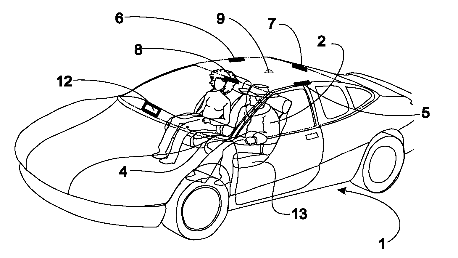
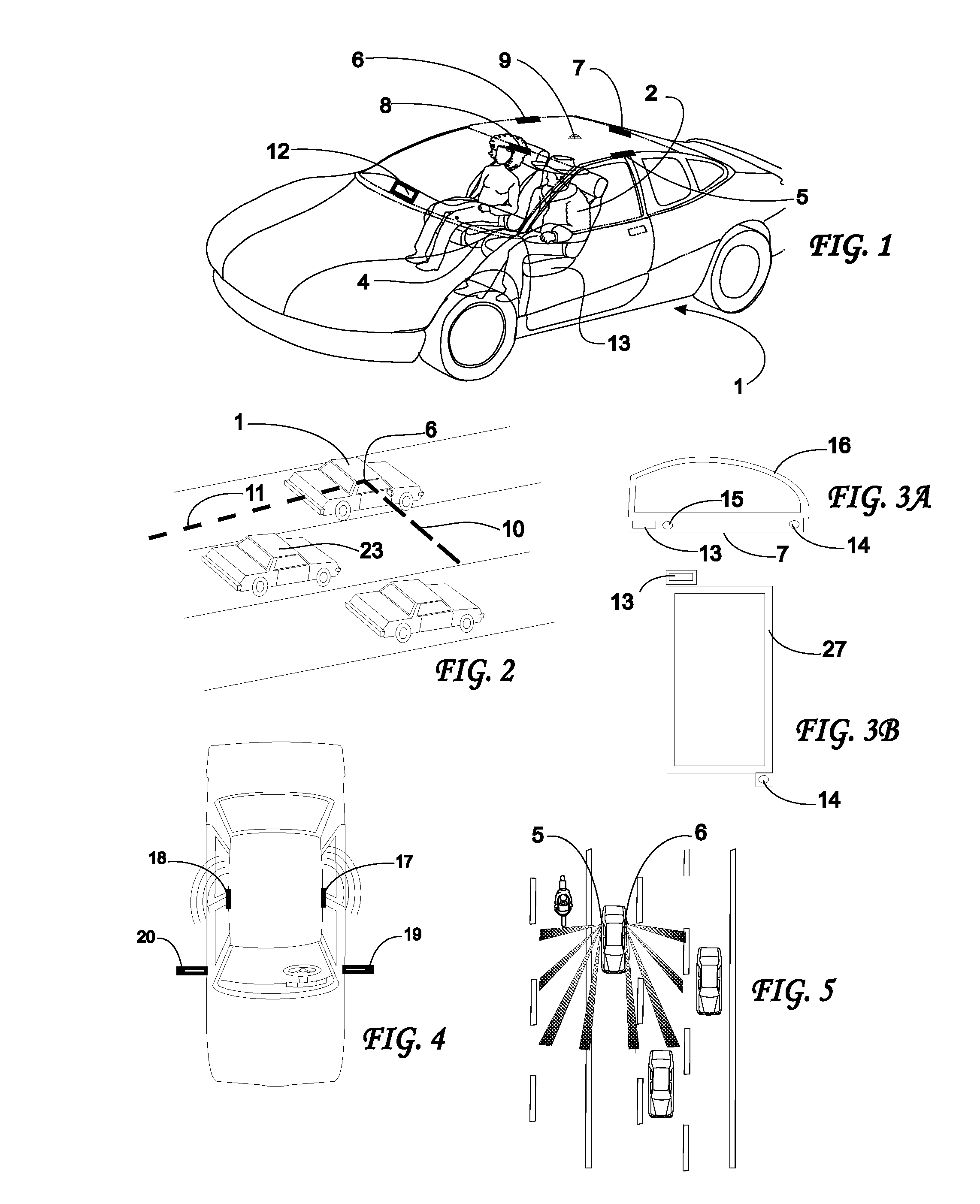
[0274]Referring now to the drawings wherein the same reference numerals refer to like elements, a perspective semi-transparent view of an automobile is shown generally as 1 in FIG. 1. A driver 2 of the automobile sits on a front seat 4. Five transmitter and / or receiver assemblies 5, 6, 7, 8 and 9 are positioned at various places with views of the environment surrounding the vehicle. A processor such as control circuitry 12 is connected to the transmitter / receiver assemblies 5-9 by appropriate wires, not shown, or wirelessly and controls the transmission of waves or energy from the transmitter portion of the assemblies 5-9 and captures the return signals received by the receiver portion of the assemblies 5-9. Control circuitry 12 usually contains one or more analog to digital converters (ADCs) or frame grabbers, a microprocessor containing sufficient memory and appropriate software including pattern recognition algorithms, and other appropriate ...


PUM


Abstract

Externally deployed airbag system for a vehicle including one or more inflatable airbags deployable outside of the vehicle, an anticipatory sensor system for assessing the probable severity of an impact involving the vehicle based on data obtained prior to the impact and initiating inflation of the airbag(s) in the event an impact above a threshold severity is assessed, and an inflator coupled to the anticipatory sensor system and the airbag for inflating the airbag when initiated by the anticipatory sensor system. The airbag may be housed in a module mounted along a side of the vehicle, in a side door of the vehicle (both for side impact protection), at a front of the vehicle (for frontal impact protection) or at a rear of the vehicle (for rear impact protection). Also, the externally deployed airbag can be deployed to cushion a pedestrian's impact against the vehicle.

Description

CROSS-REFERENCE TO RELATED APPLICATIONS[0001]This application is a divisional of U.S. patent application Ser. No. 11 / 926,192 filed Oct. 29, 2007 which is:1. a continuation-in-part (CIP) of U.S. patent application Ser. No. 11 / 183,598 filed Jul. 18, 2005, now U.S. Pat. No. 7,359,782, which is:[0002]A. a CIP of U.S. patent application Ser. No. 10 / 180,466 filed Jun. 26, 2002, now U.S. Pat. No. 6,918,459, which is a CIP of U.S. patent application Ser. No. 10 / 097,082 filed Mar. 13, 2002, now U.S. Pat. No. 6,749,218, which is a CIP of U.S. patent application Ser. No. 09 / 825,173 filed Apr. 3, 2001, now U.S. Pat. No. 6,623,033, which is:[0003]1) a CIP of U.S. patent application Ser. No. 09 / 024,085 filed Feb. 17, 1998, now U.S. Pat. No. 6,209,909, which is a CIP of U.S. patent application Ser. No. 08 / 247,760 filed May 23, 1994, now abandoned; and[0004]2) a CIP of U.S. patent application Ser. No. 09 / 307,883 filed May 10, 1999, now U.S. Pat. No. 6,343,810; and[0005]B. a CIP of U.S. patent appli...

Claims


Application Information

Patent Timeline
Patent Type & Authority Applications(United States)
IPC IPC(8): G06F19/00B60R21/0134G01S13/931G01S17/931
CPCA01C7/102G01S2013/9353B60R21/0134B60R21/23138B60R21/36B60R2021/0004B60R2021/0006B60R2021/0018B60R2021/23107B60R2021/23153G01S7/023G01S13/931G01S17/936G01S2013/9332G01S2013/9378G01S2013/9385G08G1/166G01S2013/9314G01S2013/9321G01S2013/9342B60R19/205G01S2013/9318G01S2013/93274G01S2013/93272G01S2013/932G01S2013/9315G01S17/931
Inventor BREED, DAVID S.
Owner AMERICAN VEHICULAR SCI
Learn More