
Ltcc substrate structure and method for the production thereof

a cofired ceramic and substrate technology, applied in the direction of ceramic shaping apparatus, special surfaces, electric devices, etc., can solve the problems of defective transition nature, kirkendall voiding, cavity formation, etc., and achieve the effect of reducing the transition, simple and cost-effectiv

Active Publication Date: 2010-03-11
MICRO SYST ENG
View PDF6 Cites 8 Cited by
  • Summary
  • Abstract
  • Description
  • Claims
  • Application Information

AI Technical Summary

Benefits of technology

[0014]The object of the present invention is therefore to disclose an LTCC substrate structure which has a reliable contact element that renders the application of a plating process superfluous or at least minimizes it. The object is further to disclose a simple and cost-effective method for producing an LTCC substrate structure.
[0016]The advantage of a substrate structure according to the invention is that a diffusion barrier layer can be applied so exactly locally that a subsequent application of a second metal layer is made possible. The advantage of the solution according to the invention lies in avoiding transition vias which tend to a mushroom-like growth in the mixed metal technology. Furthermore, the application of the error-prone plating technology can be avoided or reduced to a low proportion. A further metal layer can then be applied onto a diffusion barrier layer with any local or integral methods.

Problems solved by technology

However, this is very cost-intensive.
If the gold pad and the silver-containing metallization lie one on top of the other, the problem arises that the noble metals gold and silver, which have different diffusion rates, come into direct contact, so that with the diffusion of both noble metals into one another a volume change occurs that causes a cavity formation (so-called Kirkendall voiding).
The cavity formation can lead to a defective nature of the transition and thus to an interruption of the electrical connection, which cannot be tolerated in all of the substrates used in particular in medical technology.
However, a plating process of this type requires a large investment of time in the development of the process for the concrete application.
Furthermore, the process is very error-prone.
Moreover, there is the problem with plating that the baths used for the plating have to be loaded continuously in order to avoid a lasting change in their composition (transition).
For smaller enterprises a production line that contains a plating step is therefore very expensive.
The integral plating process is therefore not suitable for the application of the diffusion barrier layer in the case of small throughputs.

Method used


Image

  • Ltcc substrate structure and method for the production thereof
  • Ltcc substrate structure and method for the production thereof
  • Ltcc substrate structure and method for the production thereof

Examples


Embodiment Construction

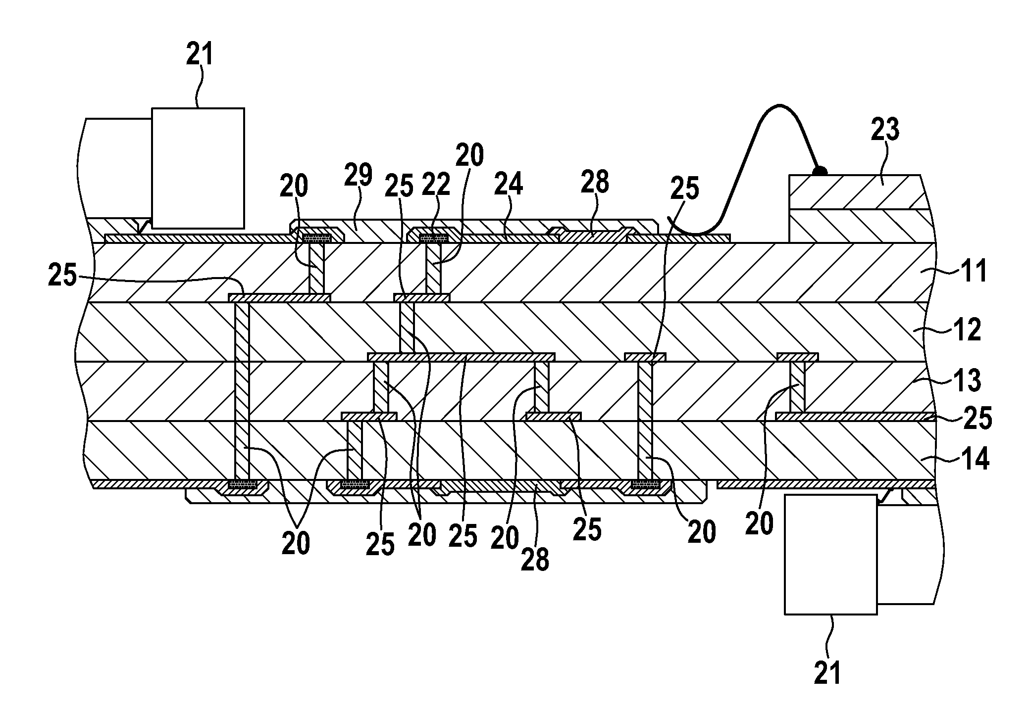
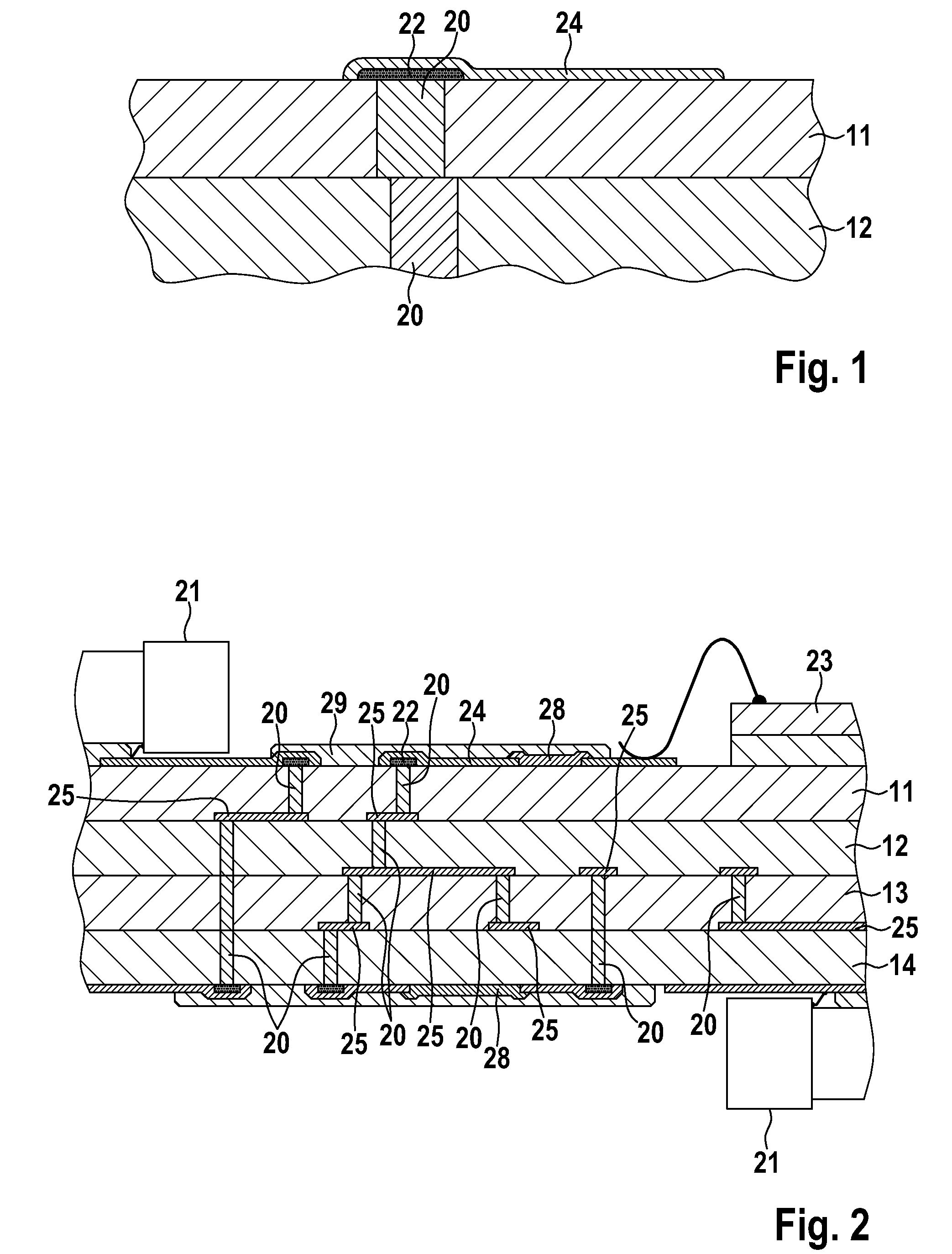
[0035]The first exemplary embodiment in FIG. 1 shows two substrate layers 11, 12 lying one on top of the other, which were produced by means of LTCC. First metallizations in the form of silver through-hole platings (Ag via) 20 run through the first layer 11 and the second layer 12 of the substrate structure according to the invention, which through-hole platings connect the conductor structures beneath to the conductor structures or components arranged on the surface of the substrate structure. The through-hole platings 20 are embodied essentially cylindrically, wherein the through-hole plating 20 running through the substrate layer 11 forms part of the surface of the substrate structure lying above.

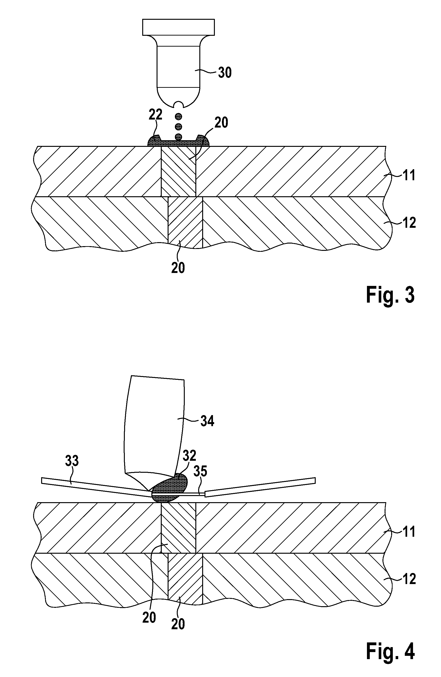
[0036]A diffusion barrier layer (also referred to below as a passivation layer) 22 is arranged on the through-hole plating 20 running in the upper substrate layer 11, which diffusion barrier layer contains nickel and / or a nickel alloy. This is locally applied by means of printing or disp...


PUM

PropertyMeasurementUnit
Temperatureaaaaaaaaaa

Abstract

An LTCC substrate structure with at least one contact element for connecting a wire conductor, which has a first metallization (20) arranged on and / or in the ceramic substrate for electrical connection to the wire conductor, wherein the first metallization (20) preferably contains silver or a silver alloy. To avoid via posting or a plating process, a diffusion barrier layer covering the first metallization or metal layer, which diffusion barrier layer (22) covering the first metallization (20), which diffusion barrier layer is produced with a locally acting application method, and a second metal layer (24) arranged on the diffusion barrier layer (22) are provided, wherein the second metal layer (24) preferably contains gold and / or platinum and / or an alloy that has at least one of these elements. The invention also discloses a production method for an LTCC substrate structure of this type.

Description

[0001]This application takes priority from German Patent Application DE 10 2008 041 873.0, filed 8 Sep. 2008, the specification of which is hereby incorporated herein by reference.BACKGROUND OF THE INVENTION[0002]1. Field of the Invention[0003]Embodiments of the invention relate to a low temperature cofired ceramics (LTCC) substrate structure with at least one contact element for connecting a wire conductor, which has a first metallization arranged on and / or in the ceramic substrate, which metallization preferably contains silver or a silver alloy, for electrical connection to the wire conductor, and a method for producing a substrate structure of this type.[0004]2. Description of the Related Art[0005]Currently, substrate structures for ceramic printed circuit boards are often produced by means of the so-called LTCC technology (LTCC=low temperature cofired ceramics). This technology renders possible a cost-effective production of multilayer circuits with integrated passive elements ...

Claims


Application Information

Patent Timeline
IPC IPC(8): H05K1/03H05K3/00
CPCH01L21/4867H01L23/15H01L23/49811H01L23/49866H01L24/45H01L24/48H01L2224/32225H01L2224/45124H01L2224/45144H01L2224/48091H01L2224/48227H01L2224/48465H01L2224/48599H01L2224/48699H01L2224/73265H01L2224/85444H01L2924/01005H01L2924/01013H01L2924/01022H01L2924/01027H01L2924/01028H01L2924/01029H01L2924/01042H01L2924/01047H01L2924/01058H01L2924/01074H01L2924/01078H01L2924/01079H01L2924/01082H01L2924/01327H01L2924/014H01L2924/09701H01L2924/19043H05K1/0306H05K1/112H05K1/167H05K3/248H05K3/28H05K3/4061H05K3/4629H05K2201/035H01L2924/01006H01L2924/01024H01L2224/85099Y10T29/49149Y10T29/49163Y10T428/24917H01L2924/00014H01L2924/00H01L2924/00012H01L2924/15787H01L2224/48644H01L2224/48744H01L2224/85207H01L2224/05599H01L2224/85469H01L2224/45565H01L24/73H01L2924/19106H01L2924/00015H01L2224/45624H01L2924/013
Inventor SCHWANKE, DIETERZEILMANN, CHRISTIANKRENKEL, MICHAEL
Owner MICRO SYST ENG
Learn More