Elongated twin feed line RFID antenna with distributed radiation perturbations

a radiation perturbation and feed line technology, applied in the field of antennas, can solve the problems of antenna being unobtrusive when installed, adversely affecting the ability of rfid antennas to reliably read rfid tags, etc., and achieves the effects of reliable tag reading, uniform signal strength, and favorable polarization pattern

Active Publication Date: 2010-03-11
WISTRON NEWEB +1
View PDF0 Cites 29 Cited by
  • Summary
  • Abstract
  • Description
  • Claims
  • Application Information

AI Technical Summary

Benefits of technology

[0009]In the preferred embodiments, the stubs are skewed with respect to the antenna axis. The skew or angularity of the stubs relative to the axis develops a favorable polarization pattern. The feed line conductors, ideally, are disposed along a serpentine path, centered about the axis that reduces interference with radiation patterns from the stubs by orienting the stubs normal or nearly normal to the feed lines.
[0010]The preferred antenna arrangement is characterized by diversity of both electric field polarization and beam direction, and at the same time a relatively uniform signal strength coming from each radiator. This beam diversity enables the antenna to be driven and radiate at a high power level, without violating Federal Communication Commission (FCC) rules, to ensure RFID tag illumination and, therefore, reliable tag reading. The beam diversity of direction and polarization obtained by the preferred antenna construction, additionally, enhances performance by ensuring that an RFID tag in the antenna operating range with any orientation will be illuminated with an aligned polarized beam. Beam diversity is further increased by using multiple antennas to cover the same zone.
[0011]The skewed polarization and beam separation characteristic of the preferred antenna enables an identical antenna or antennas to be flipped on its axis and / or inverted relative to a first antenna to further increase the beam diversity in both polarization and direction.

Problems solved by technology

Signal fading due to interference, absorption, reflection and the like can adversely affect the ability of an RFID antenna to reliably read an RFID tag.
Additionally, the antenna should be unobtrusive when installed and, ideally, easily concealed.

Method used


Image

  • Elongated twin feed line RFID antenna with distributed radiation perturbations
  • Elongated twin feed line RFID antenna with distributed radiation perturbations
  • Elongated twin feed line RFID antenna with distributed radiation perturbations

Examples


Embodiment Construction

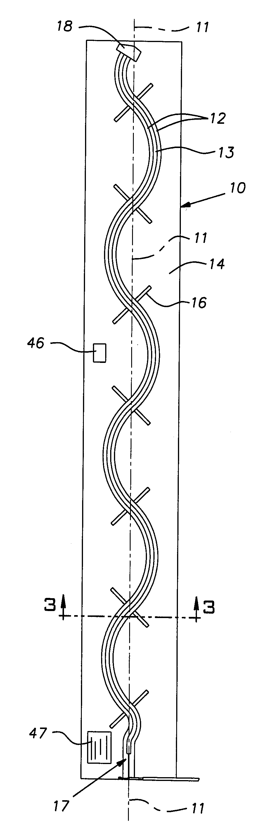
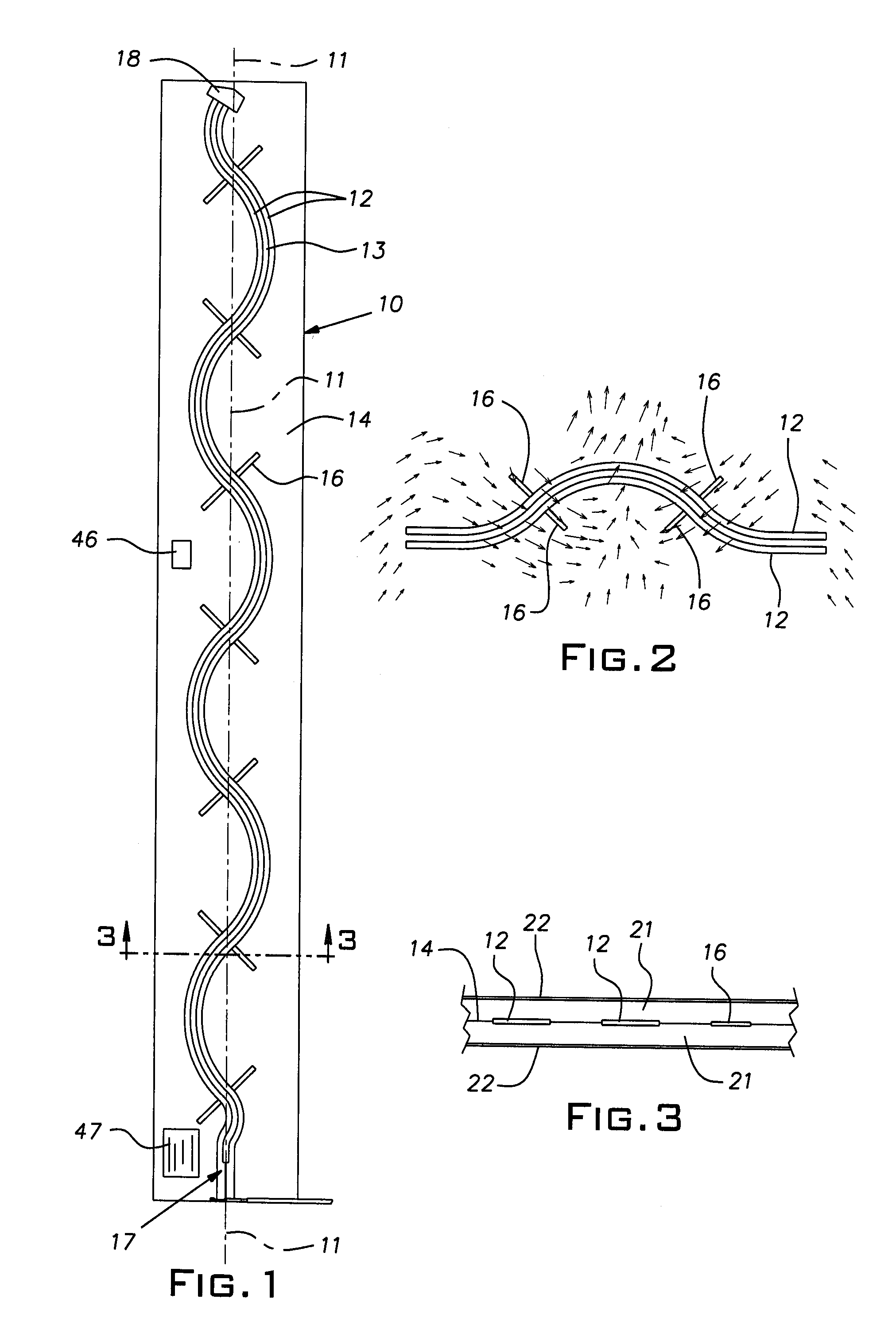
[0024]FIG. 1 illustrates a preferred form of an RFID antenna 10. The antenna is elongated along a longitudinal axis 11. The antenna 10 includes a pair of coplanar twin ribbon-like conductors or strips 12 having a gap or space 13 therebetween. The conductors 12, also referred to herein as feed lines, are made of copper or aluminum, for example, and can be relatively thin self-supporting foil or can be printed, deposited, or otherwise fabricated on a thin carrier film 14 of suitable dielectric material such as Mylar®, or etched from a printed circuit board.

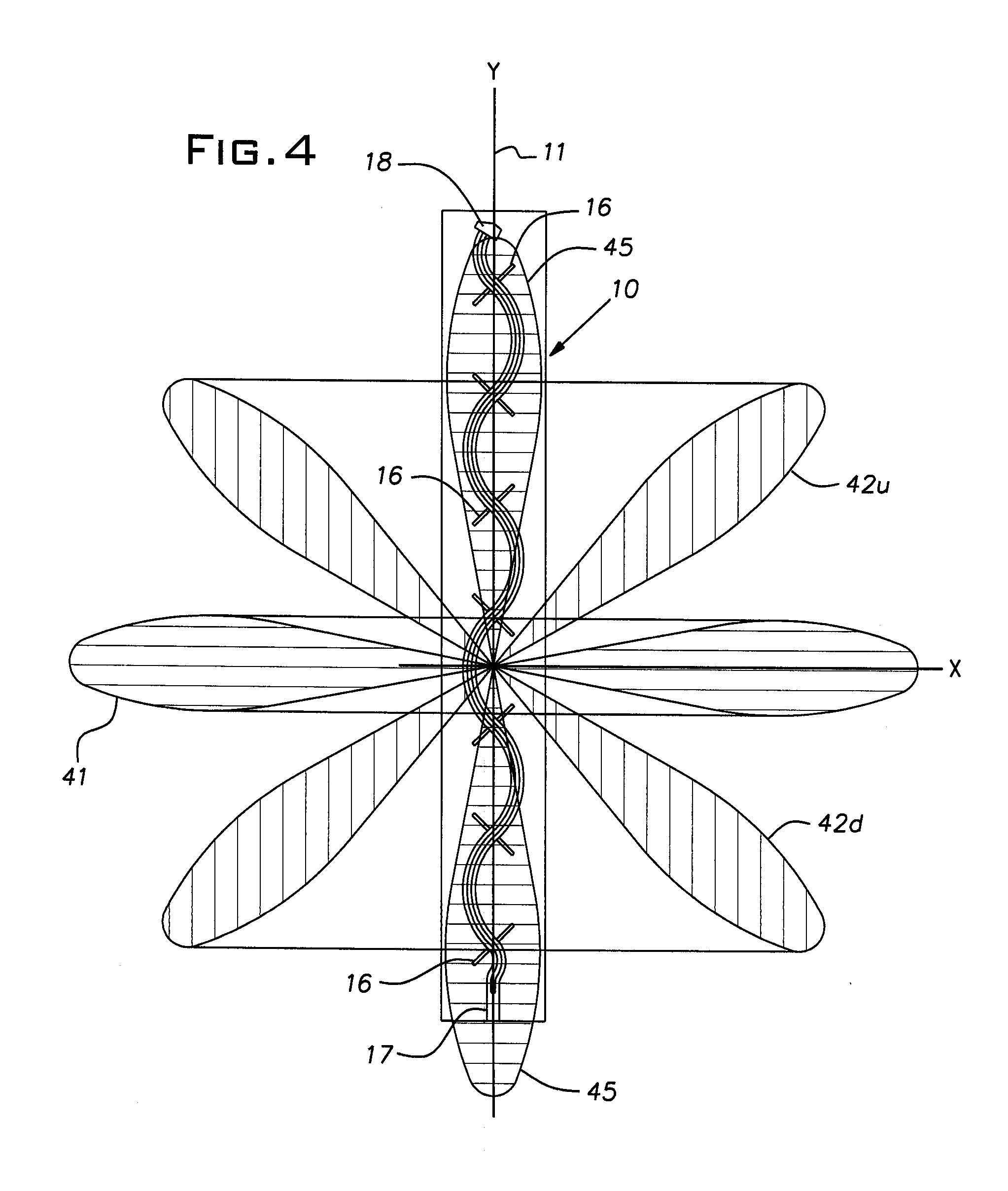
[0025]Preferably at uniformly spaced locations along the length of the antenna 10 are pairs of stubs (i.e. dipoles) or branch radiators 16, each stub of a pair being in electrical continuity with an associated one of the conductors or feed lines 12. The stubs 16 are conveniently formed conductors such as the same material used for the feed lines 12, are coplanar with the feed lines, and are integrally formed with these lines so as t...


PUM


Abstract

An RFID antenna comprising an elongated structure existing along an axis that is long compared to the signal wavelength and including twin ribbon-like feed lines of electrically conductive material, the feed lines being in a common plane and being uniformly laterally spaced from one another, and a plurality of radiating perturbations associated with the feed lines at a plurality of locations spaced along the feed lines, at each location each feed line has its own individual perturbation or portion of a perturbation.

Description

[0001]This application claims the priority of U.S. Provisional Application No. 61 / 191,687, filed Sep. 11, 2008.BACKGROUND OF THE INVENTION[0002]The invention pertains to radio frequency identification (RFID) systems and, in particular, to an improved antenna for such applications.PRIOR ART[0003]RFID technology is expected to greatly improve control over the manufacture, transportation, distribution, inventory, and sale of goods. A goal, apparently not yet realized on a widespread scale, is the identification of goods down to a unit basis at a given site. To accomplish this goal, each item will carry a unique tag that, when it receives radiation from an RFID antenna, will send back a modulated unique signal verifying its presence to the antenna. The antenna, in turn, receives this transmitted signal and communicates with a reader that registers reception of this signal and, therefore, the presence and identity of the subject item.[0004]Typically by its nature, an RFID tag identifying...

Claims


Application Information

Patent Timeline
Patent Type & Authority Applications(United States)
IPC IPC(8): G08B13/22H01Q21/08
CPCH01Q21/005H01Q1/2216H01Q13/206H01Q21/245
Inventor BURNSIDE, WALTER D.BURKHOLDER, ROBERT J.TSAI, FENG-CHI EDDIE
Owner WISTRON NEWEB
Why Eureka
Try Eureka