

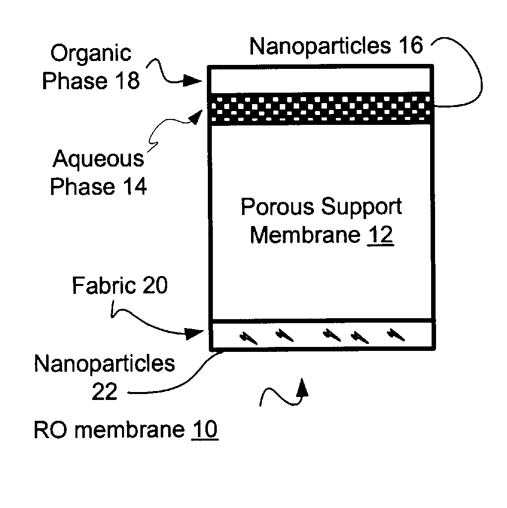
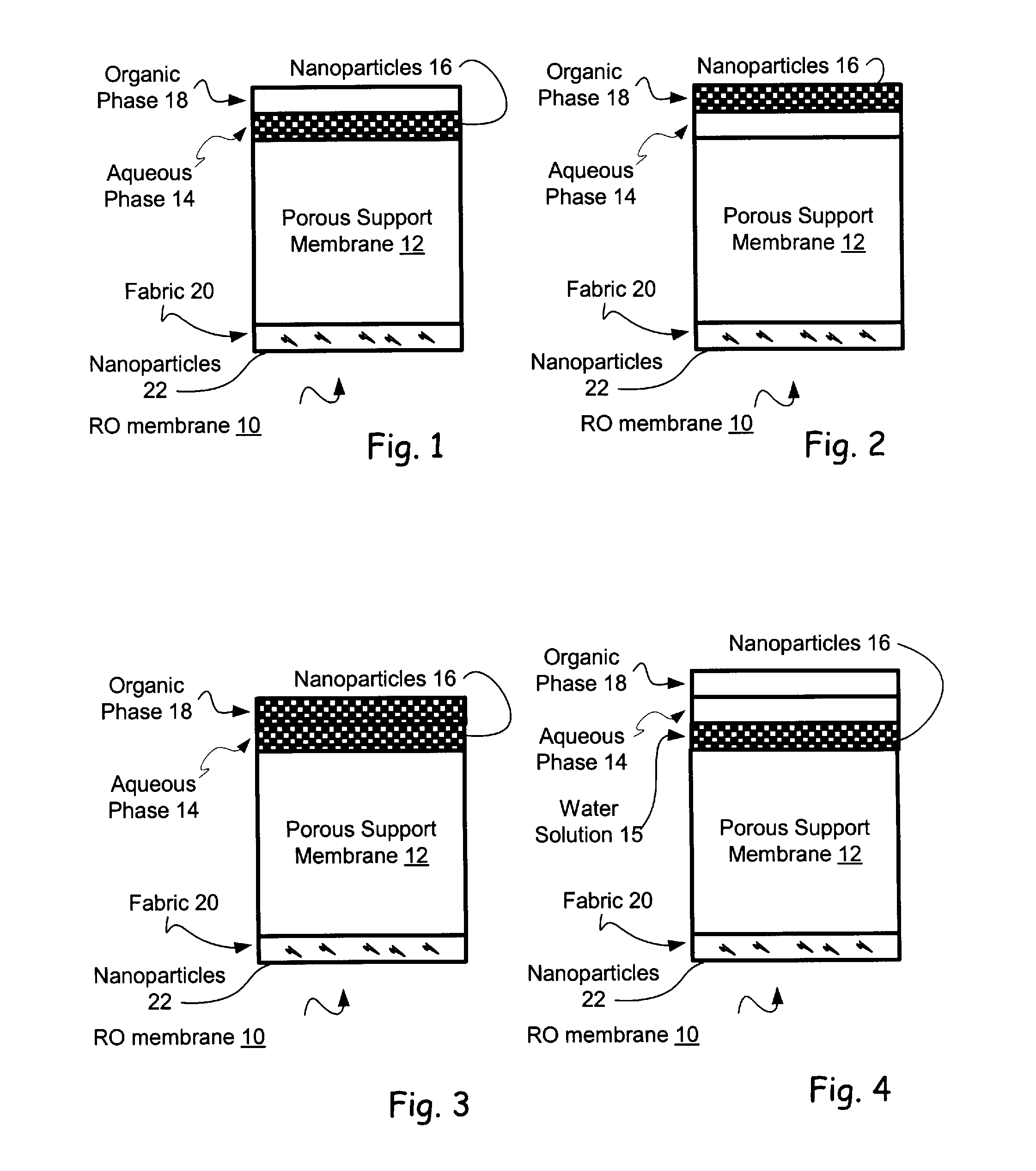
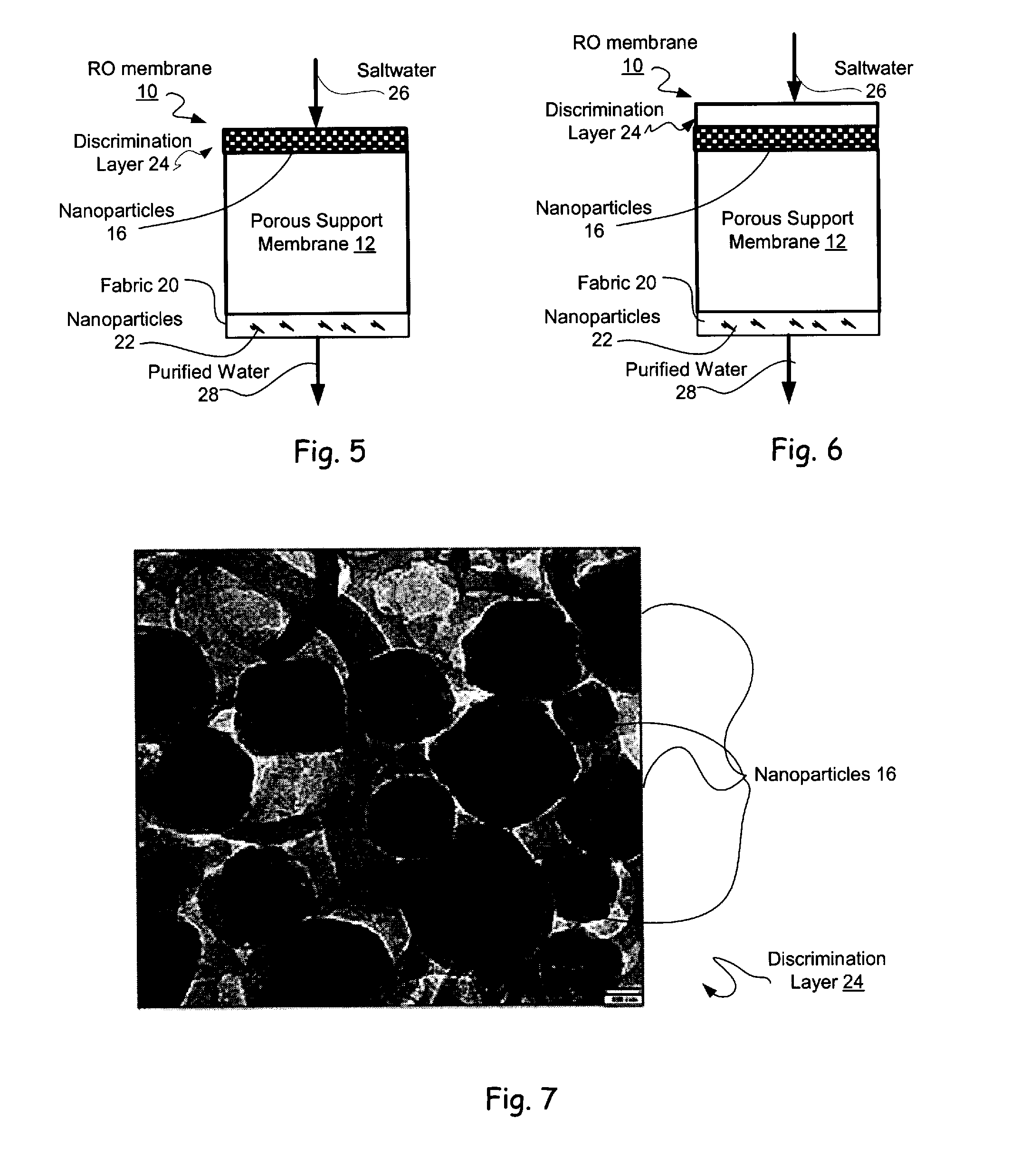
Reverse Osmosis Membranes
a reverse osmosis and membrane technology, applied in the direction of membranes, filtration separation, separation processes, etc., can solve the problems of reduced flux, limited success, and inability to reduce the rejection characteristics
- Summary
- Abstract
- Description
- Claims
- Application Information
AI Technical Summary
Benefits of technology
Problems solved by technology
Method used
Image

Examples
example a
[0230]Two aqueous solutions of 3.2 wt % MPD, 4.5 wt % triethylammonium camphorsulfonate (TEACSA) and 0.06 wt % sodium lauryl sulfate (SLS) in DI water were prepared, one of them also contained 0.1% of LTA (150 nm diameter). The solution with LTA was sonicated for 30 mins. An Isopar G solution with 0.3 wt % TMC was also prepared.
[0231]A piece of wet polysulfone support was placed flat on a clean glass plate. An acrylic frame was then placed onto the membrane surface, leaving an area for the interfacial polymerization (IP) reaction to take place.
[0232]Then 50 mL of an aqueous MPD solution prepared as described previously was poured onto the framed membrane surface and remained there for 1 minute. The solution was drained by tilting the frame until no more solution dripped from the frame.
[0233]The frame was taken off, and was left horizontally for at least 4 minutes at which point most of the surface water had evaporated. The membrane was then clamped with the glass plate in four corne...
example b
[0236]A continuous coating process: an aqueous dispersion of LTA (300 nm) was added to an aqueous solution of composition similar to that used in a laboratory batch reaction (4 wt. % MPD). The final solution turbidity was 21 nephelometric turbidity units (NTU). All other solutions and processing conditions were unchanged. This continuous process included brief application of a vacuum, which led to the concentration of LTA particles at the surface of the support membrane.
LTAFluxContact(300 nm)(gfd)Rejectionanglenone17.799.40%50.721 NTU26.998.80%36.7
example c
[0237]Two aqueous solutions of 4.0 wt % MPD, 4.5 wt % TEACSA and 0.2 wt % SLS in DI water were prepared, one also contained 0.05 wt. % of LTA (80 nm diameter). The solution with LTA was sonicated for 30 mins. An Isopar G solution with 0.3 wt % TMC was also prepared.
[0238]A piece of wet polysulfone support was placed flat on a clean glass plate. An acrylic frame was then placed onto the membrane surface, leaving an area for the IP reaction to take place.
[0239]An aqueous MPD solution (50 ml) prepared as described previously was poured onto the framed membrane surface and remained for 1 minute. The solution was drained by tilting the frame until no solution dripped from the frame.
[0240]The frame was taken off, and was left horizontally for at least 4 minutes at which point most of the surface water had evaporated. The membrane was then clamped with the glass plate in four corners. An air knife was used to finish drying of the membrane surface. The membrane was reframed using another cl...
PUM
| Property | Measurement | Unit |
|---|---|---|
| thickness | aaaaa | aaaaa |
| time | aaaaa | aaaaa |
| temperature | aaaaa | aaaaa |
Abstract
Description
Claims
Application Information