Diesel catalyst system

a catalyst system and diesel technology, applied in the direction of machines/engines, mechanical equipment, surface coverings, etc., can solve the problems of inability to meet the needs of ci engines, etc., to achieve the effect of high fuel consumption, increased greenhouse effect, and simple structur

Active Publication Date: 2010-03-18
VOLVO LASTVAGNAR AB
View PDF8 Cites 27 Cited by
  • Summary
  • Abstract
  • Description
  • Claims
  • Application Information

AI Technical Summary

Benefits of technology

[0006]The efficiency of an SCR catalyst, related to the driving cycle, is limited to about 65-80 percent, and its function is severely impaired by the presence of soot. For exhaust after-treatment of soot emission, a filter is used; such a filter does however require regeneration at intervals varying with engine load conditions. The regeneration mostly means that the exhaust temperature is increased by any means, e.g. by extremely late fuel injection, a post injection, by inlet air throttling, or by any other suitable means. The increased exhaust temperature allows soot particles trapped in the filter to “burn off”, i.e. react with oxygen in the exhausts to form carbon dioxide and water. However, every regeneration sequence results in a fuel economy penalty. Present and future legislation concerning N0χ emissions will make it virtually necessary to combine late fuel injection, SCR systems and soot filters. This leads to a “vicious circle”, ultimately resulting in a high fuel consumption, which in turn leads to an increased greenhouse effect and a bad driving economy.
[0007]If the NOx exhaust aftertreatment could be improved, then the vicious circle should be broken; the fuel injection timing could be set to a setting giving a minimum fuel economy, from which would follow decreased soot formation, which in turn would make NOx reduction easier.
[0008]It is desirable to provide an exhaust aftertreatment system enabling a high NOx conversion factor.

Problems solved by technology

For SI (spark ignition) engines, the emissions can hardly be regarded as a problem after the three-way catalyst was put on the market in the mid 70:s. For CI (compression ignition) engines, the situation is, however, slightly more complicated; CI engines have inherently high emission levels of nitric oxides (NOx) and particles (soot).
One obstacle concerning exhaust aftertreatment for reducing NOx in CI engine exhausts is the presence of oxygen; as implied earlier, a large amount of air is inducted in the cylinders prior to fuel injection.
Hence, there is always a surplus of air in the cylinders, compared to the amount of air necessary to completely combust all the injected fuel.
An air surplus in the exhausts makes it impossible to use a standard three-way catalyst in order to reduce NOx emissions.
Soot (or particles) is / are also a major problem for CI engines; soot forms, as mentioned, in fuel rich combustion zones.
High fuel injection pressures, that form small fuel droplets, can reduce soot formation significantly, but there are design limitations on how high injection pressure that can be accepted.
The NOx reduction comes, however, with some severe penalties, namely that both soot formation and fuel consumption increase with later injection timing.
Unlike three-way catalysts for SI engines, SCR systems cannot work in an environment consisting of exhausts only; some additional agent, e.g. a reductant, must be added to the exhaust gas.
The efficiency of an SCR catalyst, related to the driving cycle, is limited to about 65-80 percent, and its function is severely impaired by the presence of soot.
However, every regeneration sequence results in a fuel economy penalty.
This leads to a “vicious circle”, ultimately resulting in a high fuel consumption, which in turn leads to an increased greenhouse effect and a bad driving economy.

Method used


Image

  • Diesel catalyst system
  • Diesel catalyst system
  • Diesel catalyst system

Examples


Embodiment Construction

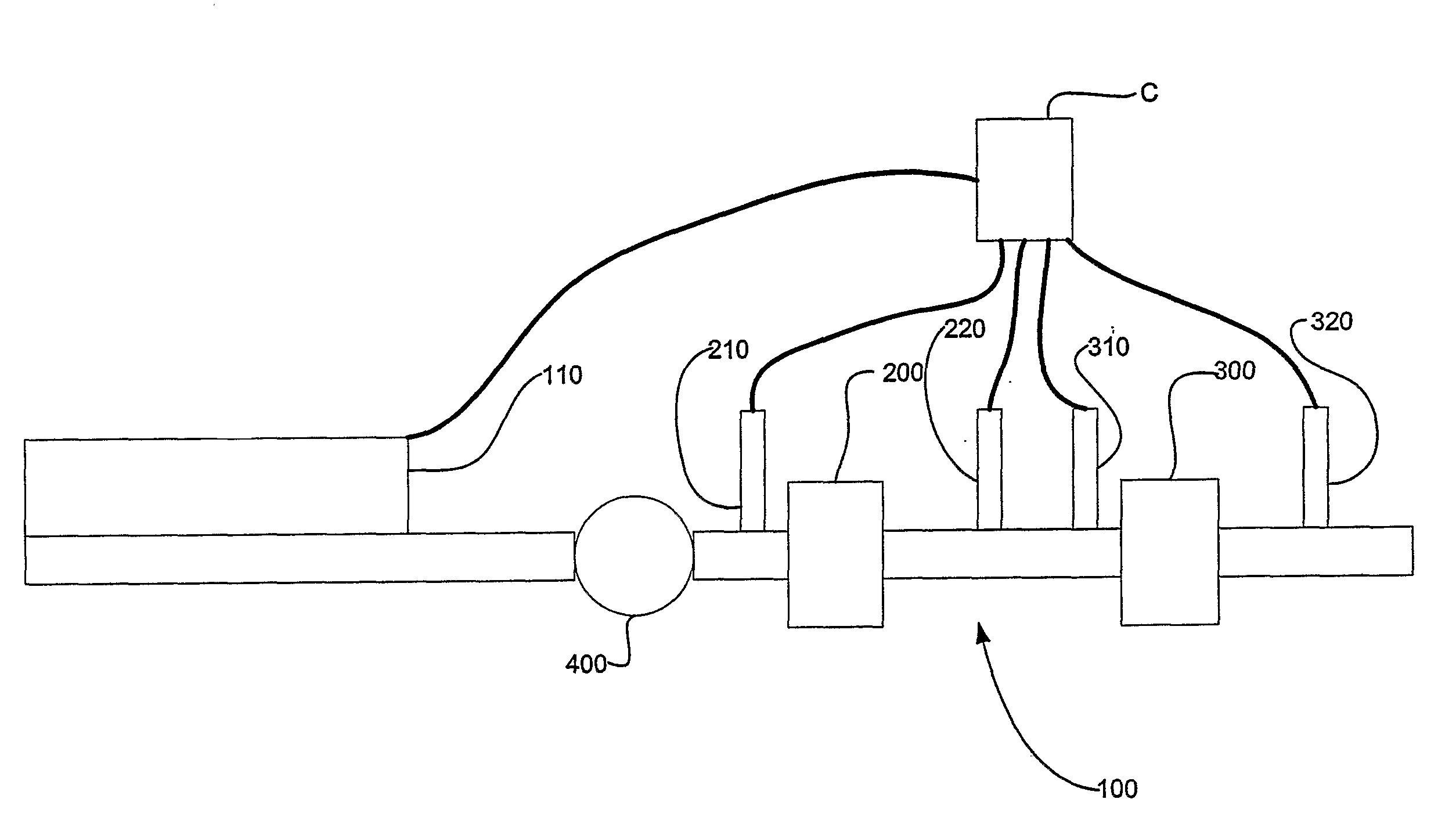
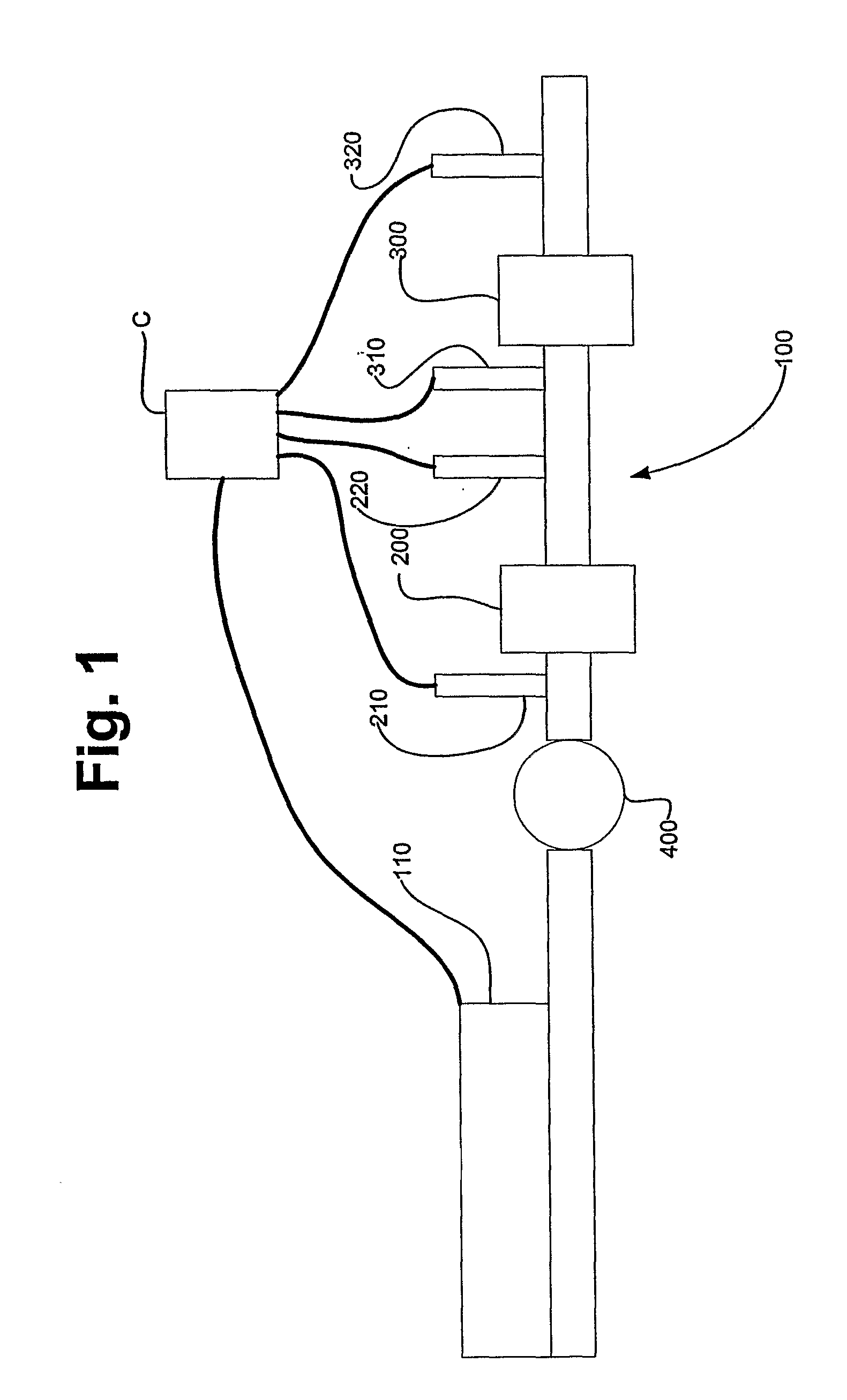
[0017]In FIG. 1, a schematic view of a catalyst system 100 according to the present invention is shown. The catalyst system 100 is connected to an exhaust system of an engine 110 and comprises a first catalyst 200, the design of which will be described later, a second catalyst 300, and an exhaust pressure governor (EPG) 400. Moreover, first and second reductant injectors 210 and 310, respectively, are mounted upstream the first catalyst 200 and upstream the second catalyst 300, respectively. The reductant may e.g. be urea, hydrocarbons, hydrogen, or any other suitable species with reducing properties. NOχ- and for NH3 sensors 220, 320 are mounted downstream the first and second catalysts, 200, 300, respectively. Alternatively, the first NOx- and for NH3 sensor 220 could be omitted.

[0018]Both catalysts 200 and 300 are so called SCR (Selective Catalyst Reduction) catalysts, whose function is well known by persons skilled in the art and briefly described above in the prior art section....


PUM


Abstract

A selective catalytic reduction system for reducing nitric oxides emission levels from a compression ignition engine includes a first reductant injector located upstream a first catalyst including a selective catalytic reduction coating. A second reductant injector is located downstream the first catalyst; and a second catalyst is placed downstream the second reductant injector and includes a selective catalytic reduction coating.

Description

BACKGROUND AND SUMMARY[0001]The present invention relates to a selective catalytic reduction system for reducing nitric oxide emission levels from a compression ignition engine, comprising a first reductant injector located upstream a first catalyst comprising a selective catalytic reduction coating.[0002]In the art of combustion engines, there has been a growing concern regarding emissions, at least since the early 1970's. For SI (spark ignition) engines, the emissions can hardly be regarded as a problem after the three-way catalyst was put on the market in the mid 70:s. For CI (compression ignition) engines, the situation is, however, slightly more complicated; CI engines have inherently high emission levels of nitric oxides (NOx) and particles (soot). Due to the nature of the engine combustion in a CI engine, a large amount of air is namely inducted into the cylinders, whereupon the air is compressed. Thereafter, an amount of fuel varying as a function of engine load is injected ...

Claims


Application Information

Patent Timeline
Patent Type & Authority Applications(United States)
IPC IPC(8): F01N3/20F01N3/10
CPCF01N3/035F01N3/106F01N3/208F01N2240/36F01N2510/06F01N2560/021F01N13/0093F01N2610/02F01N2610/1453F01N2610/146F01N2900/0411Y02T10/24F01N2560/026Y02T10/12
Inventor HINZ, ANDREASJANSSON, JONASBERNLER, HANSGOBERT, ULRICH
Owner VOLVO LASTVAGNAR AB
Why Eureka
Try Eureka