Self contained water-to-water heat pump

a heat pump and self-contained technology, applied in heat pumps, lighting and heating apparatus, heating types, etc., to achieve the effect of preventing coolant freezing, reducing the cost of implementation, and reducing the cost of operation

Inactive Publication Date: 2010-03-18
SLAUGHTER JAMES WILLIAM
View PDF15 Cites 30 Cited by
  • Summary
  • Abstract
  • Description
  • Claims
  • Application Information

AI Technical Summary

Benefits of technology

[0009]More specifically, one advantage of the system is that there is no need to drill or alter the landscape to provide a location for ground loops, thus, the system is less expensive to implement. Embodiments of the present invention are also self-contained wherein a single conduit system is employed that includes segments of varying temperatures that define the vapor compression cycle. In addition, due to the system's size and lack of external componentry, it may be located indoors, thereby avoiding outside exposure concerns such as temperature fluctuations and moisture. Further, since hot water (i.e. hotter than the fluid heated by the ground that enters the heat pump in a traditional system), is directed into the heat pump as the source of heat energy, the mass flow through the heat pump may be slowed dramatically. More specifically, prior art systems require a source mass flow of about 12-15 gallons per minute to prevent the coolant in the evaporator from freezing. In embodiments of the present invention, the temperature of the source fluid is about 95° F., thereby preventing coolant freezing. Thus the flow rate of source fluid may be slowed and a smaller more ...

Problems solved by technology

One skilled in the art will appreciate that additional compression may be needed in order to sustain the temperature of the water exiting the heat pump, but th...

Method used


Image

  • Self contained water-to-water heat pump
  • Self contained water-to-water heat pump
  • Self contained water-to-water heat pump

Examples


Embodiment Construction

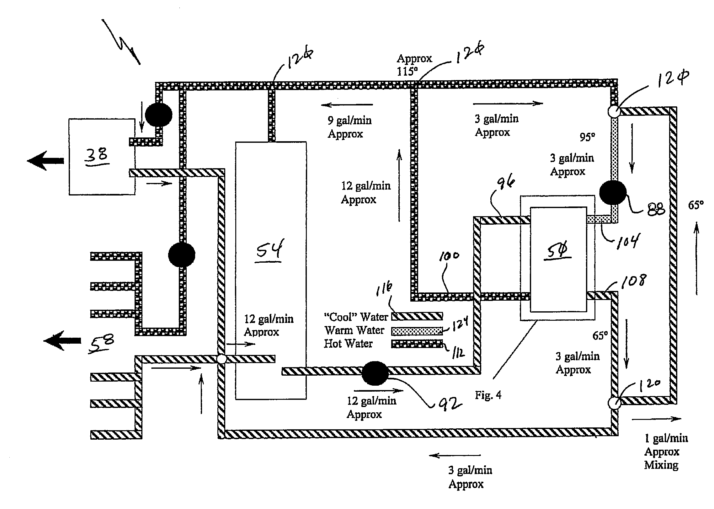
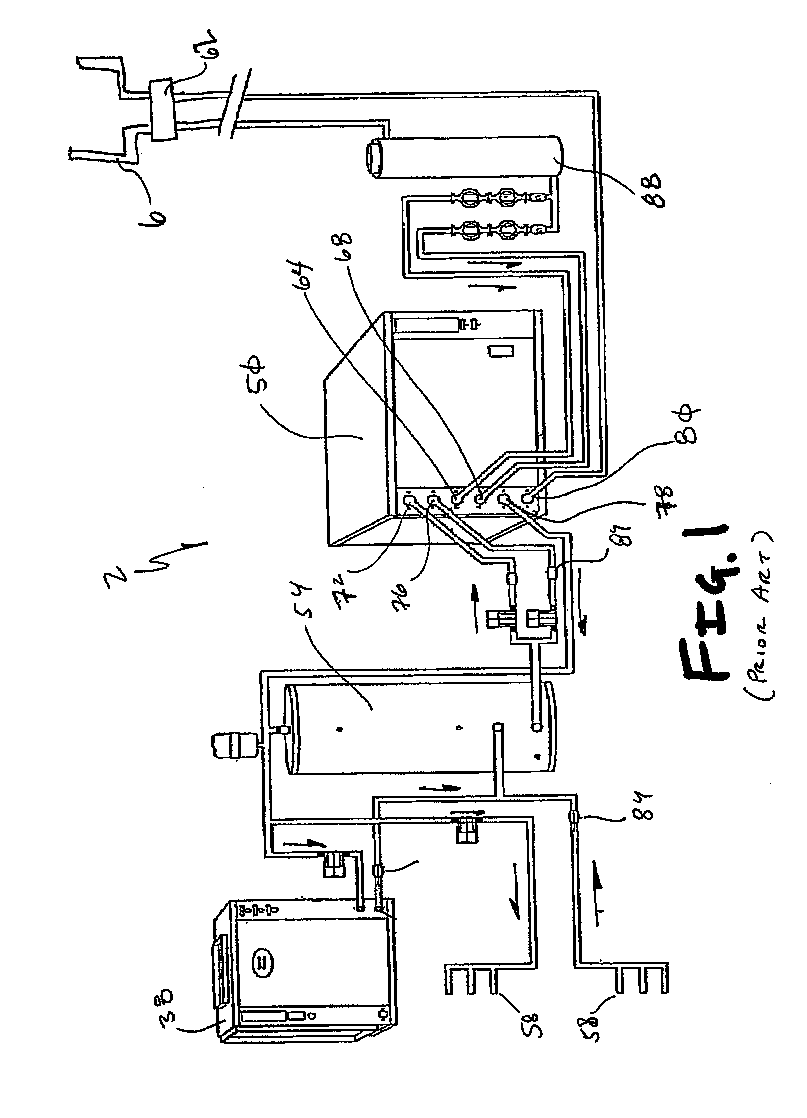
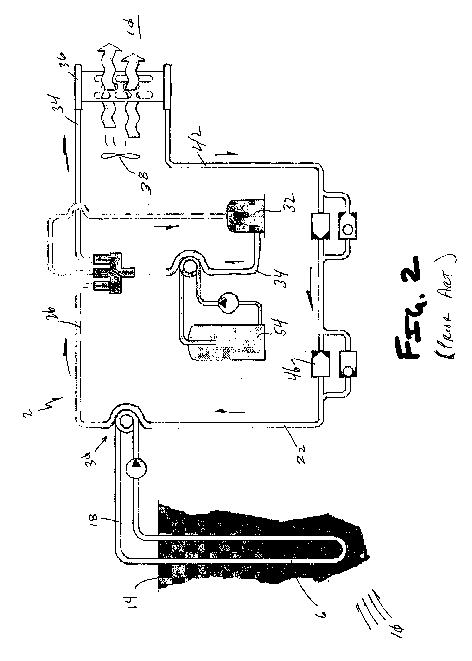
[0021]Referring now to FIGS. 1 and 2, a ground source heat exchange system 2 of the prior art is shown. More specifically, as is well understood by one skilled in the art, the prior art heating system 2 employs a ground loop 6 that is positioned either horizontally or vertically within the earth surface. The latent heat 10 of the ground 14 is transferred to the cooler fluid 18 in the ground loop 6 via heat conduction. The now heated warm fluid 18 in the loop is then placed in thermal communication with a coolant loop 22 via a heat exchanger 30 wherein the heat from the ground loop 6 is transferred to coolant contained in the coolant loop 22. The cold coolant vapor 26 produced by the heat exchanger 30 is then compressed by a compressor 32, thereby converting electro-mechanical energy into heat energy that increases the temperature of the vapor. The now hot vapor 34 is then directed to a condenser 36 wherein the heat energy may be extracted therefrom via a fan 38, for example, to heat...


PUM


Abstract

A self-contained water-to-water heat transfer system is provided that mixes hot water produced by a heat exchange with cold output fluid expelled from the heat pump to make source fluid. More specifically, in order to reduce the fluid flow rate required within a heat pump and substantially prevent freezing of evaporator coils within the heat pump, source water fed into the heat pump is taken from a mixture of the output hot water that was generated in the heat pump and the cool water exiting the heat pump. The system alleviates the need to employ a ground loop outside of a structure that is required by traditional geothermal heating systems.

Description

CROSS-REFERENCE TO RELATED APPLICATIONS[0001]This application is a continuation-in-part of U.S. patent application Ser. No. 11 / 775,739, filed Jul. 10, 2007, which claims the benefit of U.S. Provisional Patent Application Ser. No. 60 / 806,902, filed Jul. 10, 2006, the entire disclosure of each are incorporated by reference herein.FIELD OF THE INVENTION[0002]The present invention relates generally to a thermoelectric apparatus that transfers thermal energy from one location to another that can be used alternatively to either heat or cool an area.BACKGROUND OF THE INVENTION[0003]Heat pumps are basically air conditioning units that function in reverse and are commonplace in many residential and commercial structures. The most common air-to-air pumps employ a conduit filled with a thermally conductive coolant, such as Freon, that transfers heat taken from the air outside of the structure into the structure. The vapor compression cycle that facilitates the heat transfer comprises generally...

Claims


Application Information

Patent Timeline
IPC IPC(8): F25B30/00
CPCF24D3/12F24D11/0214F24D2200/12F24D2200/24Y02B30/52F25B2339/047Y02B10/40Y02B10/70Y02B30/126F25B29/003Y02B30/00
Inventor SLAUGHTER, JAMES WILLIAM
Owner SLAUGHTER JAMES WILLIAM
Why Eureka
Try Eureka