Method for operating an electrical power tool, and a drive unit for an electric power tool

a technology of electric power tools and drive units, which is applied in the direction of manufacturing tools, motor/generator/converter stoppers, ac motor stoppers, etc., can solve the problems of motor torque and torque output to the applicable tool, spindle torque output, and different torque outputs of motors

Inactive Publication Date: 2010-03-18
ROBERT BOSCH GMBH
View PDF8 Cites 43 Cited by
  • Summary
  • Abstract
  • Description
  • Claims
  • Application Information

AI Technical Summary

Benefits of technology

[0013]It is the object of the present invention to furnish a method for operating an electric power tool as well as a drive unit for an electric power tool, in which on the one hand, shutoff of the drive unit because of an overload protection is avoided upon startup or switching on of the electric power tool because of moments of inertia, and it is furthermore assured that during a startup or switching-on phase, an overly high torque is not transmitted to the tool.

Problems solved by technology

In electric power tools that have a drive unit, it is often necessary for the torque that is output, such as the spindle torque output via a spindle, to be limited in every state of operation.
However, upon changes in rpm of the drive unit of the power tool, it can happen that the motor torque and the torque output to the applicable tool differ.
Moreover, in very cold ambient temperatures, increased friction can occur at a bearing of the electric motor and / or the revolving tool holding fixture, and this friction can also contribute to tripping the limitation of the motor torque earlier than intended, because of the thus-elevated motor current.
However, in an overload situation such mechanical overload couplings often involve intensive noise, and they are moreover usually relatively expensive to make.

Method used


Image

  • Method for operating an electrical power tool, and a drive unit for an electric power tool
  • Method for operating an electrical power tool, and a drive unit for an electric power tool

Examples


Embodiment Construction

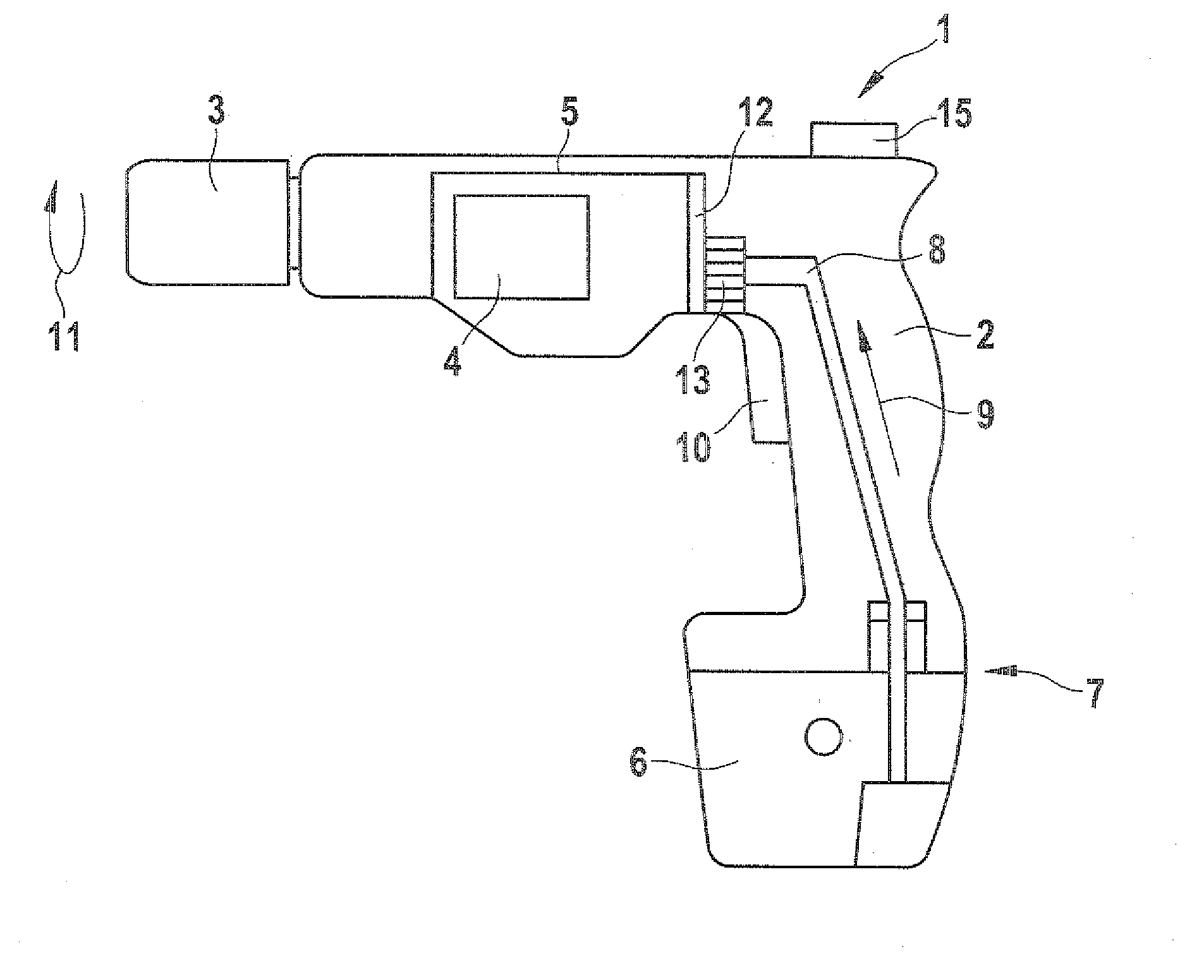
[0040]In FIG. 1, a power tool 1 is shown, which has a housing 2 in which a drive device 5 is disposed. The drive device 5 is coupled with a tool holding fixture 3 directly or via a gear (not shown), so that the tool holding fixture 3 is driven by the drive device 5. The coupling between the tool holding fixture 3 and the drive device S is rigid, and no mechanical devices are provided for undoing the rigid connection, for instance for torque limitation.

[0041]For furnishing a driving torque, an electric motor 4 is provided in the drive device 5 and is triggerable with a suitable motor current via a triggering device 12 for furnishing a motor torque. The triggering unit 12 is connected to a motor controller 13 that is coupled to a hand control element 10 such as a trigger type element, so that a user, by actuating the hand control element 10 and by specifying a default motor voltage, can manually adjust the rpm to be adjusted by the power tool 1. The motor controller 13, via the trigge...


PUM


Abstract

The invention relates to a method for operating a handheld electric power tool, having an electric motor that is drivable at a rated torque as the maximum allowable motor torque by the application of a maximum allowable motor current. The method includes the steps of manually furnishing a specification of a maximum torque, in which the maximum torque is within a setting range between a minimum set torque and the rated torque, operating the electric motor by applying a motor voltage which corresponds to an rpm desired by the user, and limiting the motor current to a current value that depends on the furnished specification of the maximum torque.
The invention also related to a drive unit for an electric power tool, which includes an electric motor drivable at a rated torque as a maximum allowable motor torque by application of a maximum allowable motor current. A setting element manually furnishes a specification of a maximum torque, the maximum torque being within a range between zero and the rated torque. A triggering unit operates the electric motor by applying a motor voltage that corresponds to an rpm desired by the user. A motor controller limits the motor current to a current value that depends on the furnished specification of the maximum torque.

Description

CROSS-REFERENCE TO RELATED APPLICATION[0001]This application is based on German Patent Application 10 2008 040 096.3 filed Jul. 2, 2008.BACKGROUND OF THE INVENTION[0002]1. Field of the Invention[0003]The invention relates to a method for operating a handheld electric power tool, having a drive unit. The invention also relates to a drive unit for an electric power tool having a torque limiter.[0004]2. Description of the Prior Art[0005]In electric power tools that have a drive unit, it is often necessary for the torque that is output, such as the spindle torque output via a spindle, to be limited in every state of operation. To that end, a torque monitor and a torque limiter are as a rule provided.[0006]In an electrically operated power tool, such as a cordless screwdriver, such torque monitoring and torque limitation can be attained by providing that the current which is applied to a drive unit is switched off as soon as the motor current exceeds a previously fixed current threshold....

Claims


Application Information

Patent Timeline
Patent Type & Authority Applications(United States)
IPC IPC(8): B25B23/147B23Q5/18B25B21/00
CPCB25B23/147H02P1/18H02P29/028H02P29/027H02P7/285H02P29/032
Inventor LOHR, GUENTER
Owner ROBERT BOSCH GMBH
Why Eureka
Try Eureka