Compressive composite seals for sofc applications

a composite seal and compressive technology, applied in the field of compressive composite seals, can solve the problems of inability to apply in the area, high cost of silver brazing, and inability to achieve the effect of enhancing the properties of the seal and unique and superior seal

Inactive Publication Date: 2010-03-18
UCHICAGO ARGONNE LLC
View PDF12 Cites 9 Cited by
  • Summary
  • Abstract
  • Description
  • Claims
  • Application Information

AI Technical Summary

Benefits of technology

[0020]In accordance with features of the invention, the novel structure and materials characteristics produce a unique and superior seal. Materials can advantageously be selected with different thermal expansion coefficients to take advantage of residual stresses further enhancing the properties of the seal.

Problems solved by technology

One of the major issues in building planar SOFC stacks is the development and application of seals.
If a seal is electrically conductive, it cannot be applied in areas that would short-circuit the cells.
Some of the problems that occur with using glass seals; they tend to react with other fuel cell materials over time, are subject to cracking on repeated or rapid heating cycles, or have to low a viscosity and readily flow from the sealing area.
Brazes using silver are expensive, but seal at low temperatures.
The nickel type brazes often must be heated over 1000° C. to seal, which adds to the cost and time of assembling a stack.
The gaskets can deform to fill in gaps due to the unevenness of ceramic cells with uniform pressure.
However, they require the application of constant pressure to make a seal and offer little spring back if pressure is released.

Method used


Image

  • Compressive composite seals for sofc applications
  • Compressive composite seals for sofc applications
  • Compressive composite seals for sofc applications

Examples


Embodiment Construction

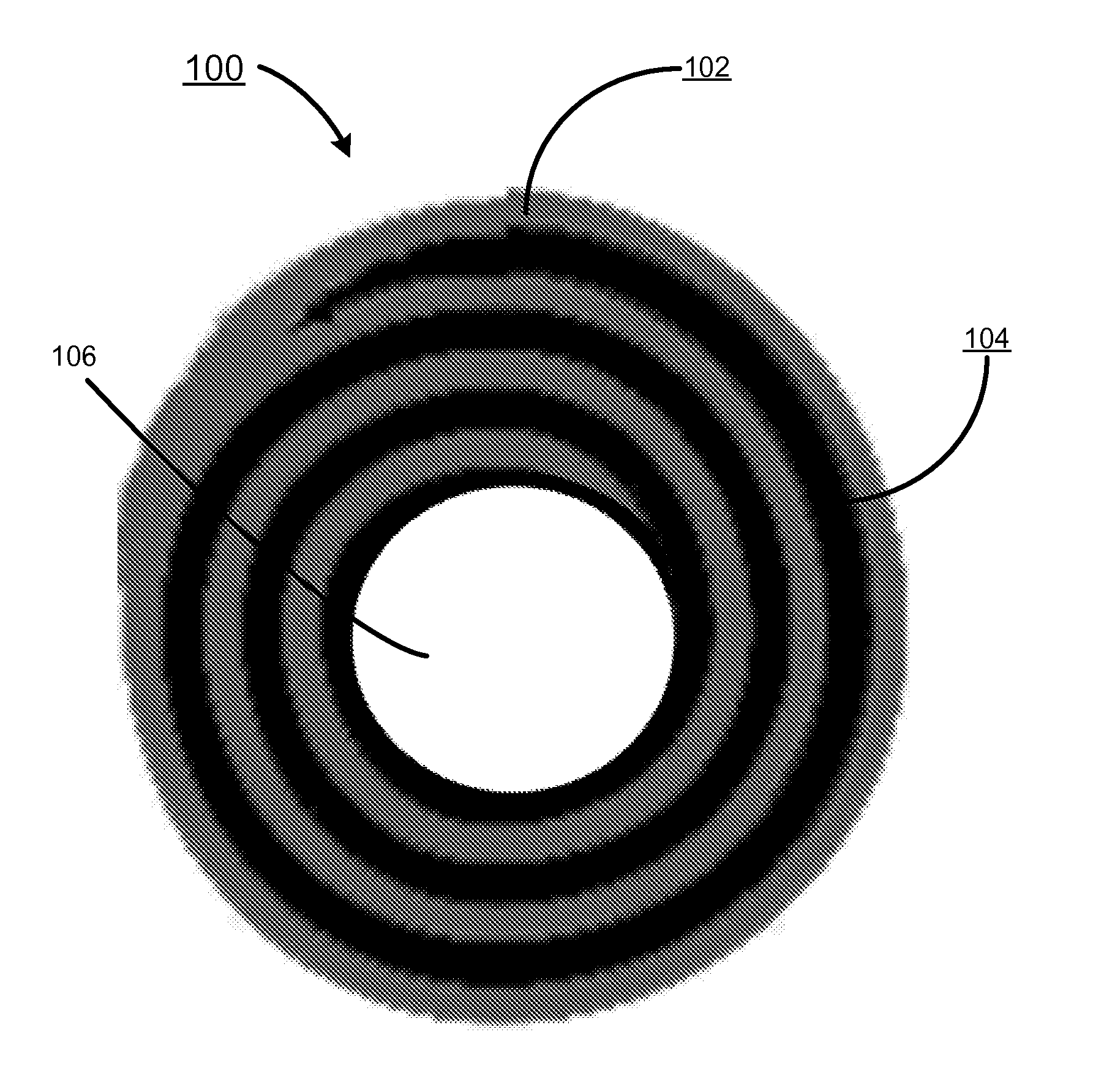
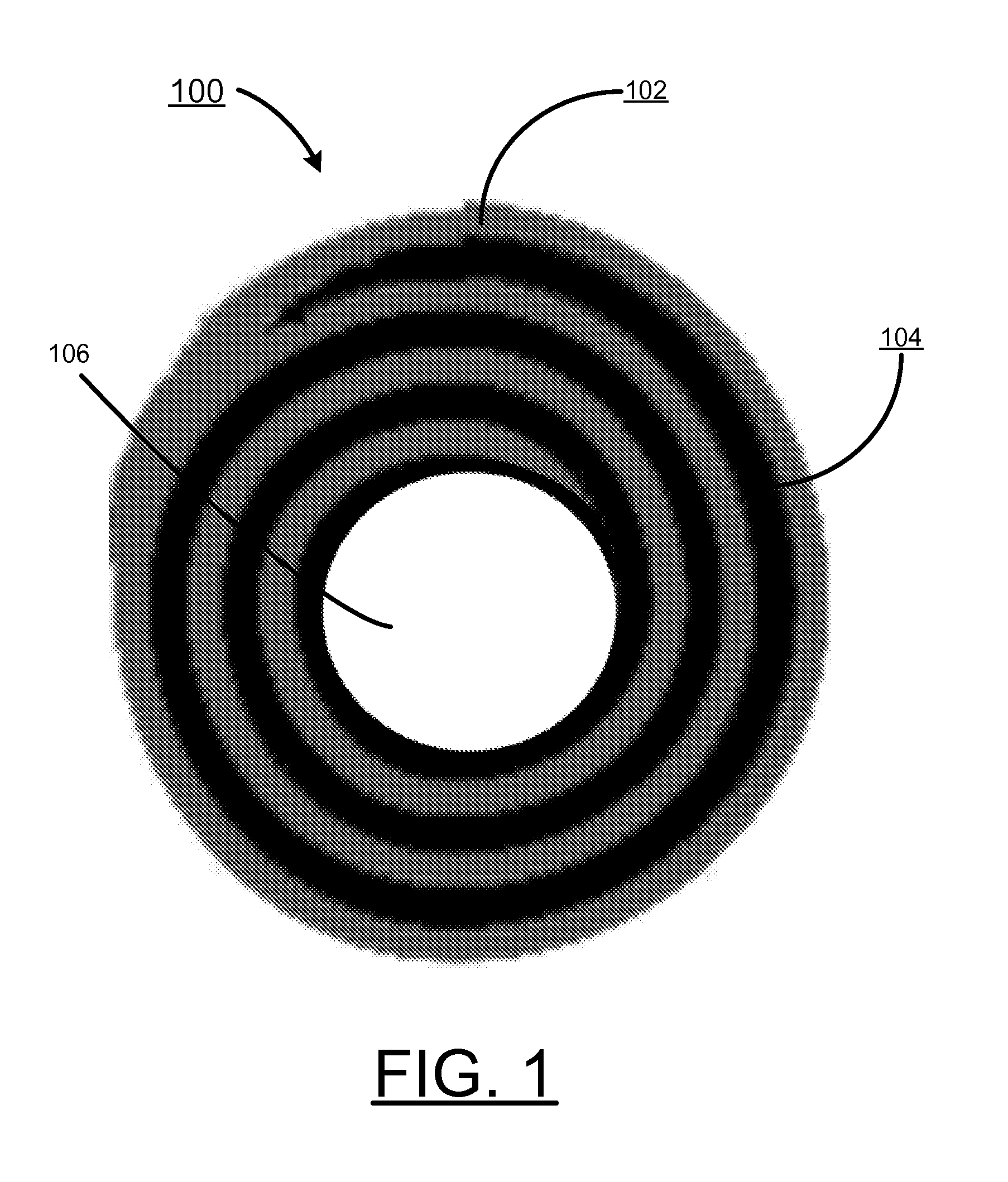
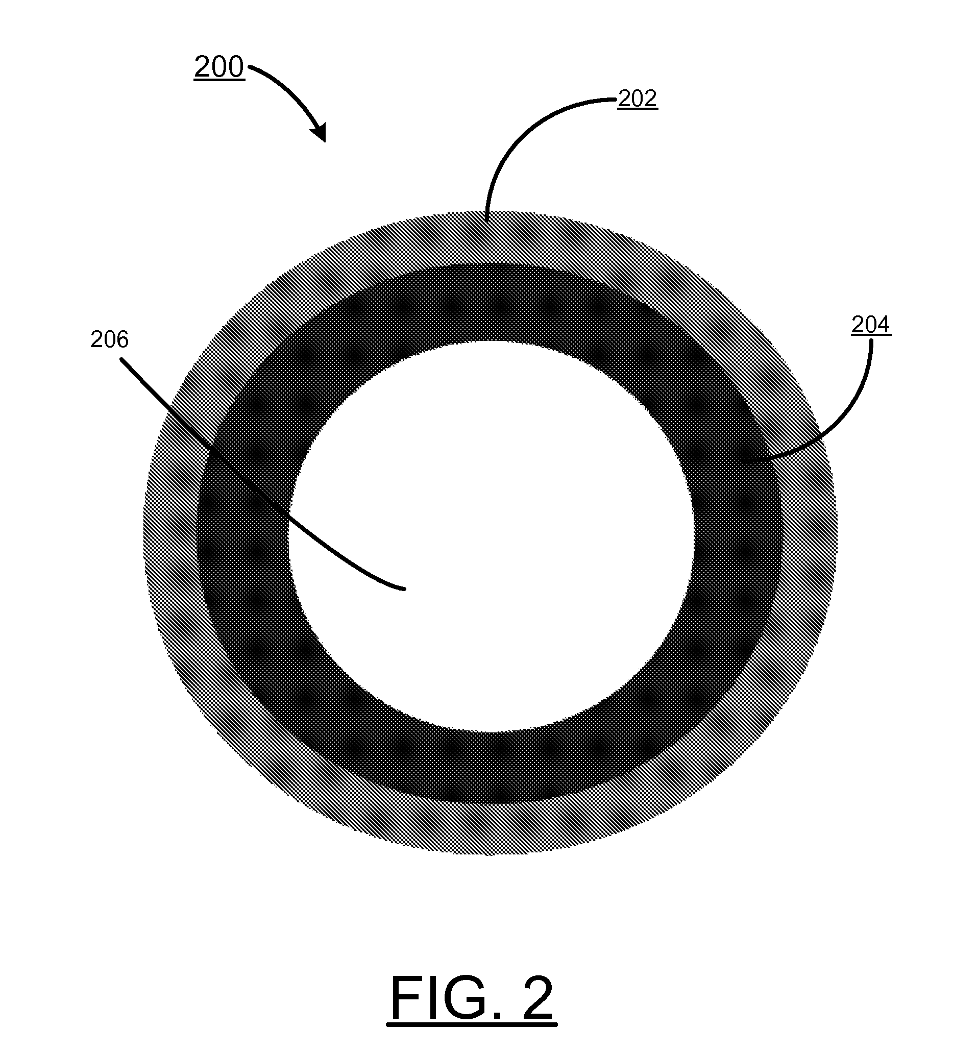
[0026]In accordance with features of the invention, a compressive composite seal structure includes a glass phase to provide a gas tight seal, and a reinforcing secondary phase to provide mechanical stability. The glass phase and the crystalline ceramic phase of the compressive composite seal structure are shaped as a layered or rolled structure with a compressive core. The compressive composite seal structure maintains an effective seal with the glass phase during all possible operating conditions of the SOFC. This glass phase of the compressive composite seal structure substantially allows the glass to effectively heal if a crack occurred during thermal cycling, providing support to the reinforcing secondary phase. The reinforcing secondary phase reduces crack propagation and provides mechanical support for the glass phase, so that if the temperature or pressure goes too high, the seal remains effective.

[0027]In accordance with features of the invention, the glass phase is a self ...


PUM

PropertyMeasurementUnit
temperatureaaaaaaaaaa
mechanical stabilityaaaaaaaaaa
compressiveaaaaaaaaaa

Abstract

Compressive composite seals for solid oxide fuel cell applications are provided. A compressive composite seal structure includes a glass phase to provide a gas tight seal, a reinforcing secondary phase to provide mechanical stability, and a compressive core. The compressive core is filled with an inert gas or air, providing a degree of compressibility, or alternatively is filled with a selected material to provide a more specific degree of compressibility and strength, such as a lower melting point glass. The compressive composite seal structure maintains an effective seal during the operating conditions of the SOFC. The self healing glass phase with the reinforcing secondary phase providing mechanical stability provides an elastic response at high temperature, effectively reduces crack propagation and if the temperature or pressure goes too high, the seal remains reliable and effective.

Description

[0001]This application claims the benefit of U.S. Provisional Application No. 61 / 097,994 filed on Sep. 18, 2008.CONTRACTUAL ORIGIN OF THE INVENTION[0002]The United States Government has rights in this invention pursuant to Contract No. W-31-109-ENG-38 between the United States Government and The University of Chicago and / or pursuant to Contract No. DE-AC02-06CH11357 between the United States Government and UChicago Argonne, LLC representing Argonne National Laboratory.FIELD OF THE INVENTION [0003]The present invention relates to solid oxide fuel cells (SOFCs), and more particularly, relates to improved compressive composite seals for solid oxide fuel cell (SOFC) and other applications, for example, that require a high temperature seal with some elastic properties.DESCRIPTION OF THE RELATED ART[0004]Solid oxide fuel cells (SOFCs) are high temperature, for example, 500-1000° C., electrochemical devices that convert the chemical energy of gaseous fuels (hydrogen, carbon monoxide, refor...

Claims


Application Information

Patent Timeline
Patent Type & Authority Applications(United States)
IPC IPC(8): F16J15/02
CPCF16J15/024F16J15/104Y02E60/525H01M2008/1293Y02E60/50H01M8/0282
Inventor CRUSE, TERRY A.KRUMPELT, MICHAELINGRAM, BRIAN J.
Owner UCHICAGO ARGONNE LLC
Why Eureka
Try Eureka