Wind turbine generator, wind turbine generator system, and power generation control method of wind turbine generator

a technology of wind turbine generator and wind turbine generator, which is applied in the control of electric generators, machines/engines, mechanical equipment, etc., can solve the problems of insufficient output power, inability to correct the wind direction, and inability to achieve sufficient output power, so as to improve power generation capability, increase costs, and accurate wind direction

Active Publication Date: 2010-03-18
MITSUBISHI HEAVY IND LTD
View PDF9 Cites 77 Cited by
  • Summary
  • Abstract
  • Description
  • Claims
  • Application Information

AI Technical Summary

Benefits of technology

[0030]Since correction of the wind direction is carried out on the basis of the accumulated data sequentially accumulated a more accurate wind direction can be acquired without increasing costs.
[0031]Moreover, since power generation control is carried out using the corrected wind di

Problems solved by technology

However, such a Doppler radar, an ultrasound anemometer, etc. are expensive, and resulting in cost problems.
However, correction has not been performed for wind direction.
Therefore, in particular, when carrying out yaw-angle control in which the nacelle orientation is adjusted such that the blade rotating surfaces follow the wind direction, the blade rotating surf

Method used


Image

  • Wind turbine generator, wind turbine generator system, and power generation control method of wind turbine generator
  • Wind turbine generator, wind turbine generator system, and power generation control method of wind turbine generator
  • Wind turbine generator, wind turbine generator system, and power generation control method of wind turbine generator

Examples


first embodiment

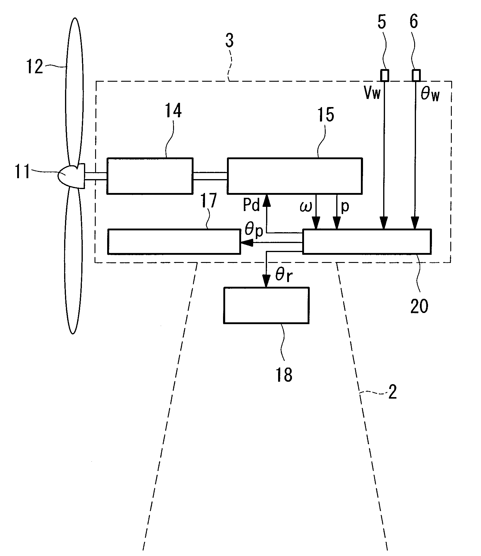
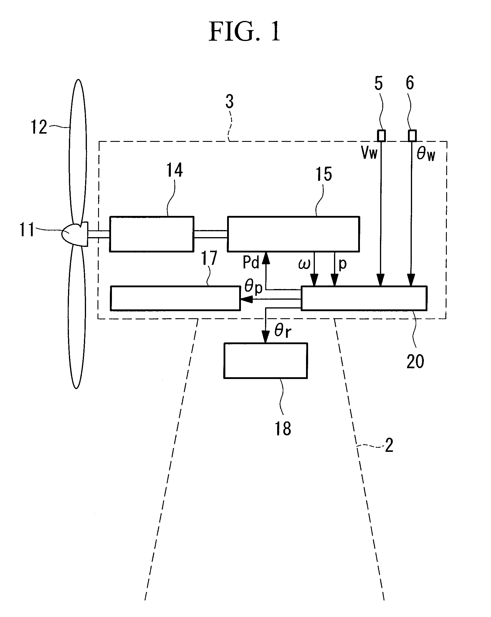
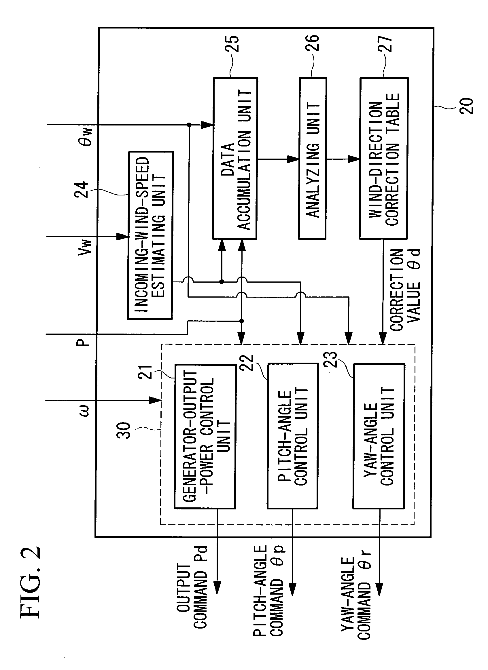
[0064]FIGS. 1 and 2 are configuration diagrams of a wind turbine generator according to a first embodiment of the present invention. FIG. 1 is a schematic configuration diagram in outline. FIG. 2 is a detailed configuration diagram of a control device shown in FIG. 1.

[0065]In FIG. 1, the wind turbine generator according to the first embodiment is constructed of an anemometer 5, an anemoscope 6, a windmill rotor 11, a windmill blade 12, a gear box 14, a power generating system 15, a pitch-angle controlling mechanism 17, a yaw-angle controlling mechanism 18, and a control device 20. In the drawing, reference numeral 2 represents a tower, and reference numeral 3 represents a nacelle.

[0066]A plurality of windmill blades 12 attached to the windmill rotor 11 rotate together with the windmill rotor 11 by receiving wind energy. Then, after acceleration by the gear box 14, the wind energy is converted to electric energy by driving a power generator in the power generating system 15 to genera...

second embodiment

[0088]Next, a wind turbine generator and a power-generation control method of a wind turbine generator according to a second embodiment of the present invention will be described. The configuration of the wind turbine generator according to the second embodiment is substantially the same as the configuration of the above-described wind turbine generator, etc. according to the first embodiment but differs in that a learning-mode control unit is provided in the control device 20.

[0089]In the first embodiment, creation and update of the wind-direction correction table 27 is carried out during operation, whereas in the wind turbine generator and the power-generation control method of the wind turbine generator according to this embodiment, the wind-direction correction table 27 is created by carrying out operation in a learning mode, different from the normal operation.

[0090]In other words, in the learning-mode control unit, the yaw-angle controlling mechanism 18 operates the wind turbi...

third embodiment

[0103]Next, FIG. 7 is a configuration diagram of a wind turbine generator system according to a third embodiment of the present invention. In FIG. 7, the wind turbine generator system according to this embodiment is a wind farm provided with M wind turbine generators 1-1 to 1-M and a central control apparatus 100 that centrally controls the operation of the M wind turbine generators 1-1 to 1-M.

[0104]The configuration, in outline, of each of the wind turbine generators 1-1 to 1-M is similar to that according to the first and second embodiments and is illustrated in FIG. 1. As a detailed configuration of control units 130-1 to 130-M, at least the incoming-wind-speed estimating unit 24 and the operation control unit 30, including the generator-output-power control unit 21 shown in FIG. 2, the pitch-angle control unit 22, and the yaw-angle control unit 23, may be provided, and other components are not required.

[0105]The central control apparatus 100 is provided with a transceiver unit 1...


PUM


Abstract

To provide a wind turbine generator, a wind turbine generator system, and a power-generation control method of a wind turbine generator that are capable of improving the power-generation capability and reducing the fatigue load on the windmill. A data accumulation unit 25 sequentially accumulates data sets of a generated output power P during operation of the wind turbine generator, an incoming wind speed Ws estimated on the basis of a wind speed measured at the anemometer, and a wind direction deviation, which is the difference between a wind direction θw measured at the anemoscope and the orientation of the nacelle; statistical analysis of the data accumulated is carried out by an analyzing unit 26; a distribution curve corresponding to the wind direction deviation of the generated output power at each incoming wind speed is determined; the wind direction deviation corresponding to the peak of the distribution curve is set as a correction value θd of the anemoscope; the correction value of the anemoscope for each incoming wind speed is stored in the wind-direction correction table 27; the wind direction Vw measured at the anemoscope is corrected with the correction value θd of the anemoscope for each incoming wind speed Ws; and power-generation control is carried out using the corrected wind direction as a control parameter.

Description

TECHNICAL FIELD[0001]The present invention relates to a wind turbine generator, a wind turbine generator system, and a power generation control method of a wind turbine generator, and, more specifically, relates to a wind turbine generator, a wind turbine generator system, and a power generation control method of a wind turbine generator that are capable of improving the power-generation capability and reducing the fatigue load on the windmill by acquiring a more accurate wind direction and providing it to the power generation control of the wind turbine generator, without increasing equipment costs.BACKGROUND ART[0002]Typically, in a wind turbine generator, wind speed and wind direction are measured using an anemometer and an anemoscope provided on a nacelle and are used as control parameters in operation control. However, since such wind speed and wind direction are measured at the downstream side of a rotor, the wind speed of the incoming wind is reduced and the wind direction dr...

Claims


Application Information

Patent Timeline
IPC IPC(8): F03D7/00F03D9/00
CPCF03D7/0204H02P2101/15F05B2240/96F05B2260/821F05B2270/32F05B2270/321F05B2270/329F05B2270/335F05B2270/80H02P9/00H02P2207/01H02P2207/05Y02E10/721Y02E10/723Y02E10/725F03D7/043Y02E10/72F03D7/02F03D7/04
Inventor HAYASHI, YOSHIYUKISHIBATA, MASAAKI
Owner MITSUBISHI HEAVY IND LTD
Why Eureka
Try Eureka