Engine room-type laser wind finding radar for multi-distance layered measurement of wind field and measurement method thereof
A wind-measuring radar and wind-measuring technology, which is applied in the field of meteorological radar detection, can solve the problems of high cost, large volume of the whole machine, poor reliability of the whole machine, etc., and achieve the effect of simple structure and high sensitivity
- Summary
- Abstract
- Description
- Claims
- Application Information
AI Technical Summary
Problems solved by technology
Method used
Image
Examples
Embodiment 1
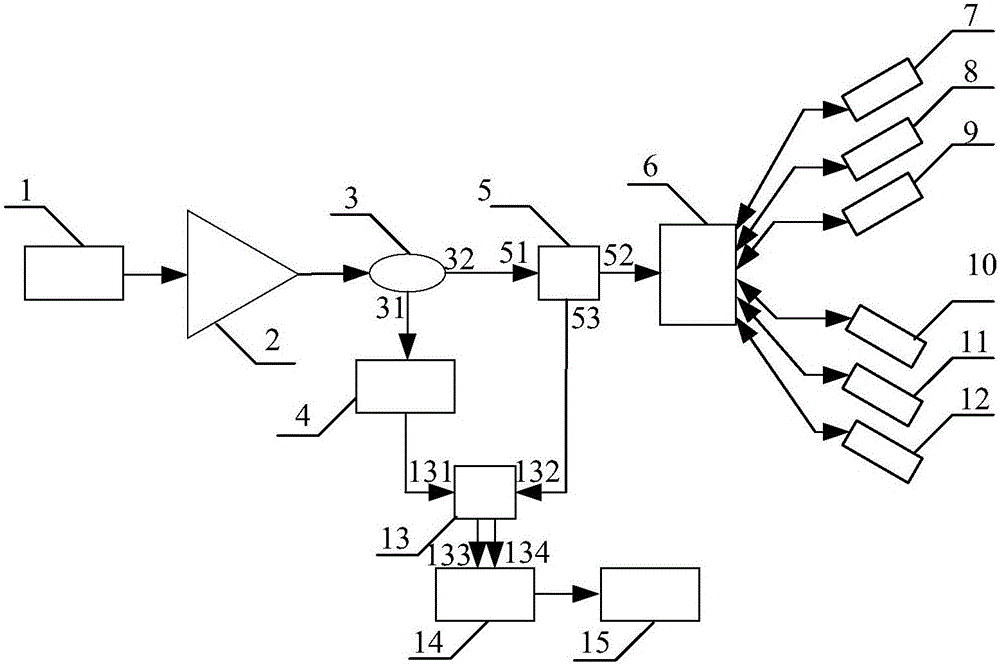
[0040] Example 1, such as figure 1 As shown, a nacelle-type laser wind radar for multi-distance and layered wind field measurement according to an embodiment of the present invention includes: a narrow linewidth seed light source 1, an optical fiber amplifier 2, an optical fiber beam splitter 3, and an acousto-optic frequency shifter 4 , fiber optic circulator 5, optical switch 6, first optical antenna 7, second optical antenna 8, third optical antenna 9, fourth optical antenna 10, fifth optical antenna 11, sixth optical antenna 12, 2×2 optical fiber beam combiner 13 , balanced photodetector 14 and signal processing circuit 15 .
[0041]The output end of the narrow line width seed light source 1 is connected with the input end of the optical fiber amplifier 2, the output end of the optical fiber amplifier 2 is connected with the input end of the optical fiber beam splitter 3, and the first output end 31 of the optical fiber beam splitter 3 is connected with the acousto-optic s...
Embodiment 2
[0050] Embodiment 2, a measurement method of a nacelle type laser wind measurement radar for multi-distance and layered measurement of wind field, is characterized in that the method comprises the following steps:
[0051] Step 1, the local oscillator light generated by the narrow-linewidth seed light source 1 passes through the optical fiber amplifier 2, then enters the acousto-optic frequency shifter 4 through the first output end 31 of the optical fiber beam splitter 3, and then enters the 2×2 optical fiber beam combiner 13 a first input terminal 131;
[0052] Step 2, the signal light generated by the narrow-linewidth seed light source 1 passes through the optical fiber amplifier 2 and enters the first port 51 of the optical fiber circulator 5 through the second output end 32 of the optical fiber splitter 3, and the signal light passes through the first port 51 of the optical fiber circulator 5 The second port 52 enters the optical switch 6, and the optical switch 6 switche...
PUM
 Abstract
Description
Claims
Application Information
 - R&D
- Intellectual Property
- Life Sciences
- Materials
- Tech Scout
- Unparalleled Data Quality
- Higher Quality Content
- 60% Fewer Hallucinations
Browse by: Latest US Patents, China's latest patents, Technical Efficacy Thesaurus, Application Domain, Technology Topic, Popular Technical Reports.
© 2025 PatSnap. All rights reserved.Legal|Privacy policy|Modern Slavery Act Transparency Statement|Sitemap|About US| Contact US: help@patsnap.com


