Method and Apparatus for Allocating Electricity from a Distributor

a technology of distributors and distribution channels, applied in the direction of emergency power supply arrangements, process and machine control, instruments, etc., can solve the problems of limited circuitry and none of the signals thus derived to the variable control of specific current loads in those environments, and achieve the effect of increasing the degree of freedom available and being more cost-effectiv

Active Publication Date: 2010-03-18
SCHULER MIKE
View PDF27 Cites 24 Cited by
  • Summary
  • Abstract
  • Description
  • Claims
  • Application Information

AI Technical Summary

Benefits of technology

[0056]The current capacity rating of an electrical power circuit is limited to the lesser of the current carrying capacity of its wires and devices and the rating of the circuit breaker connected to the supply. The arrangement of the present invention increases the degrees of freedom available in the installation of these circuits. For example, wire gauge for 80 A may be installed where a 40 A breaker services the circuit, or a new line is required, but limited to a conservative rating based on normal circuit panel considerations. Sometimes it can also be much more cost-effective to extend an existing heavy-duty circuit to a new location and use sub-panels to service existing equipment on it.
[0057]This invention provides a method and apparatus that measures the electrical current flow in one circuit breaker and makes that data available to a load applied to a different circuit breaker within the same distribution panel. It can be applied to indicate the maximum current supply available to an electric vehicle battery charger and enables the charger to adjust its current consumption accordingly. In effect the invention implements a form of electrical load shedding, or more precisely, modulated demand balancing.

Problems solved by technology

It is common for battery chargers to employ current-control circuitry, but this circuitry is limited to battery-state sensing in order to maximize battery life and prevent damage, not to the sensing of available supply current.
There are many examples of current sensor technology applied to the measurement, display and shedding of current loads in both household and industrial settings, but none appear to apply the signals thus derived to the variable control of specific current loads in those environments.

Method used


Image

  • Method and Apparatus for Allocating Electricity from a Distributor
  • Method and Apparatus for Allocating Electricity from a Distributor
  • Method and Apparatus for Allocating Electricity from a Distributor

Examples


first embodiment

gital Implementation

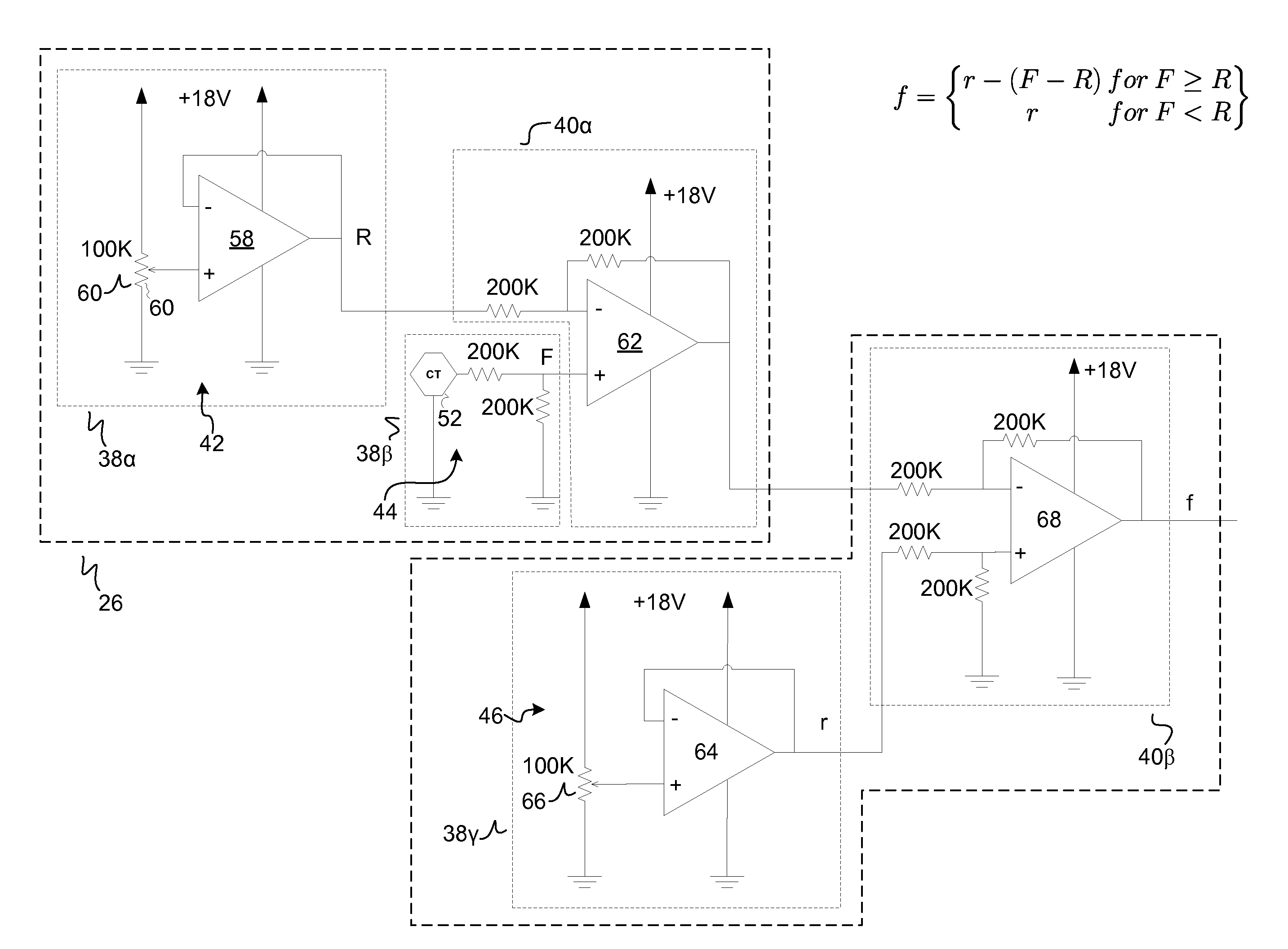
[0085]FIG. 5 shows an implementation of the embodiment of FIG. 1, wherein the means for measuring 26 and the means for limiting 28 function in a substantially digital manner, for example including means for representing the respective currents as binary values 38 and means for operating upon the binary values 40.

[0086]More particularly, in this implementation the means for representing the maximum rated current of the distributor 38α includes a memory register 48 and the means for representing the instantaneous current flowing from the distributor to the plurality of load circuits 38β includes an analog to digital converter 50 coupled to one or more current sensors 52.

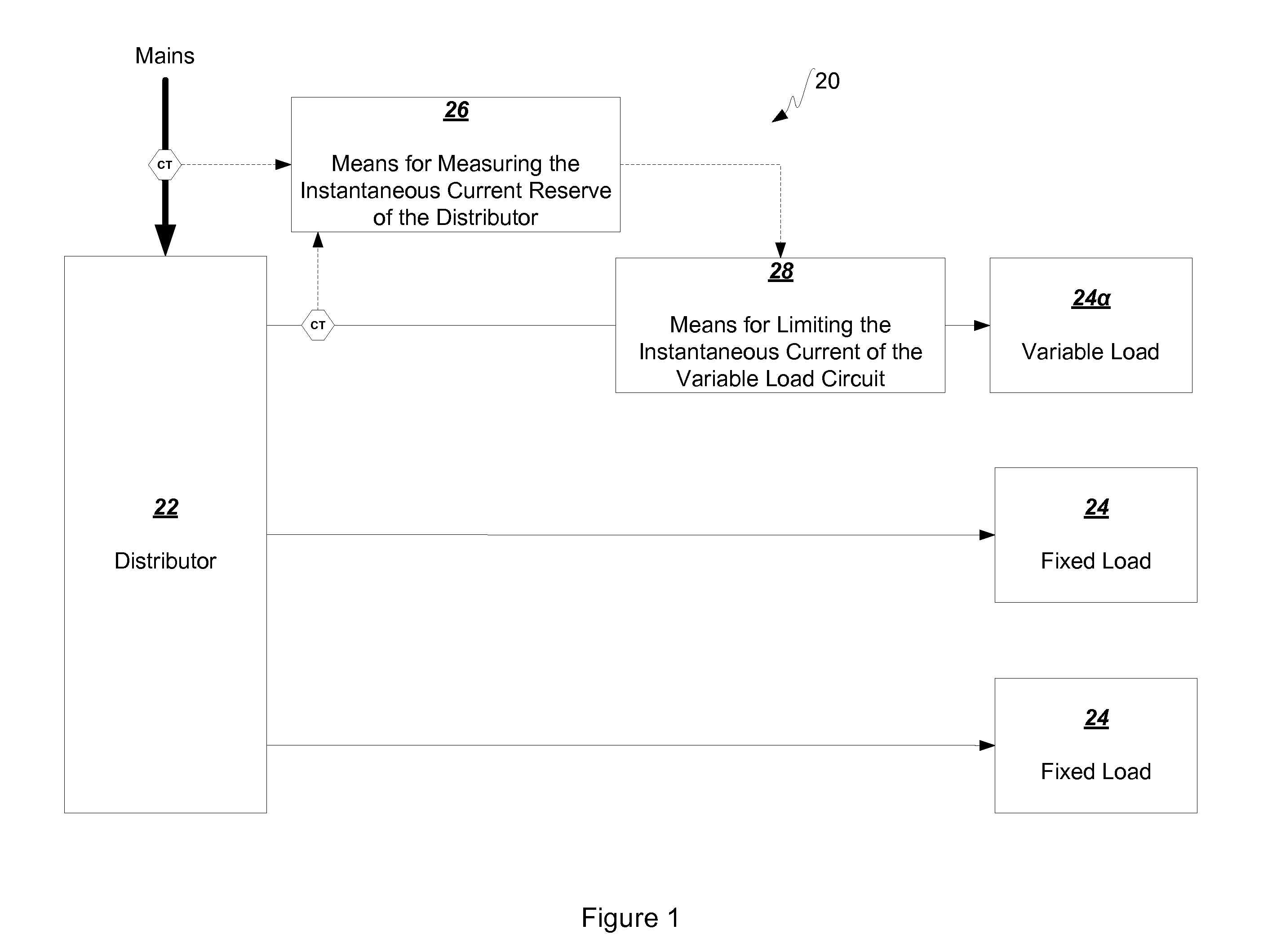
[0087]The means for measuring the instantaneous current reserve of the distributor 26 includes means for subtracting the instantaneous current flowing from the distributor from the maximum rated current of the distributor 40α.

[0088]The means for representing the full load current of the variable loa...

second embodiment

[0101]FIG. 6 shows a second embodiment of the apparatus 20, which may be viewed as an extension of the implementation of the first embodiment implementation shown in FIG. 5. In general, the second embodiment of the apparatus 20 introduces certain cost saving measures when multiple variable loads 24α are connected to the same distributor 22, in this case a distribution panel 22α.

[0102]The apparatus 20 includes both a master microcontroller module 70α and a slave microcontroller module 70β. The slave module 70β is similar to the basic elements of the first embodiment, but without user interface components. There is one such slave module 70β for each variable load circuit 24α such that there exists means for limiting 28 the respective currents of a plurality of variable load circuits 24α.

[0103]Since the most expensive components of the first embodiment are the current sensors 52, in order to reduce their aggregate cost, only the master microcontroller module 70α is configured with them...

third embodiment

[0108]FIG. 7 shows a third embodiment of the apparatus 20, which may be seen as extending concepts of the second embodiment to include current sensing using a sensor 52 applied to a distributor 22 in the form of a distribution transformer 22β servicing a distribution panel 22α which supplies load circuits 24, including at least one variable load circuit 24α. Although these transformers 22β already include fault protection, the reason for this sensor 52 is improved safety and allocation: distribution transformers 22β typically have a rating which is less than the aggregate rating of the distribution panels 22α that they supply.

[0109]The third embodiment of the apparatus 20 again comprises a master microcontroller module 70α and one or more slave microcontroller modules 70β. The function of the master module 70α is to carry out all the current sensing and to inform the slave modules 70β of its calculations. The programming of this unit is therefore almost identical to that described i...


PUM


Abstract

The present invention provides a method and apparatus for allocating current (20) from a distributor (22), having a maximum rated current, among a plurality of load circuits (24), including a variable load circuit (24α) that benefits from a full load current allocation but is operable at a lower current allocation. The invention provides for measuring the instantaneous current reserve of the distributor (22) as the maximum rated current of the distributor (22) less the instantaneous current flowing from the distributor (22) to the plurality of load circuits (24), and limiting the instantaneous current of the variable load circuit (24α) to the full load current of the variable load circuit (24α) if the instantaneous current reserve is greater than zero, and the sum of the full load current of the variable load circuit (24α) plus the instantaneous current reserve, if the instantaneous current reserve is less than or equal to zero.

Description

CROSS REFERENCE TO RELATED APPLICATION[0001]This application claims the benefit of priority from U.S. provisional application Ser. No. 61 / 188,642 filed Aug. 12, 2008 entitled “Increasing the Effectiveness of an Electric Vehicle Battery Charger”.BACKGROUND OF THE INVENTION[0002]1. Field of the Invention[0003]The present invention relates to allocating current from a distributor. More particularly, the present invention relates to allocating current from a distributor having a maximum rated current capacity, among a plurality of load circuits, including a variable load circuit that benefits from a full load current allocation but is operable at a lower current allocation, for example a charging circuit for an electric vehicle battery.[0004]2. Description of the Related Art[0005]Electrical distributors, for example distribution panels, are conventionally designed such that the aggregate current carrying capacity of all branch circuits is significantly higher than that of the main circu...

Claims


Application Information

Patent Timeline
Patent Type & Authority Applications(United States)
IPC IPC(8): G05F1/10
CPCH02J9/002H02J7/042H02J7/007Y04S20/20Y02B70/30H02J7/04
Inventor SCHULER, MIKE
Owner SCHULER MIKE
Why Eureka
Try Eureka