Stator for electrical rotating machine

a rotating machine and rotating technology, applied in the direction of dynamo-electric machines, magnetic circuit rotating parts, magnetic circuit shape/form/construction, etc., can solve the problem of increasing the magnitude of a main flux, and achieve the effect of improving the output characteristic of the electrical rotating machin

Inactive Publication Date: 2010-03-18
HONDA MOTOR CO LTD
View PDF3 Cites 14 Cited by
  • Summary
  • Abstract
  • Description
  • Claims
  • Application Information

AI Technical Summary

Benefits of technology

[0019]According to this configuration, in addition of the weld (first weld) disposed at the connection part, a second weld at the tooth part may be further provided. This further decreases the leaked magnetic flux at an inner circumferential part of the stator in magnitude in addition to the magnetic flux leaked to the holding member, so that an effective magnetic flux interlinked with the rotor of the electrical rotating machine can be increased in magnitude with improvement in output characteristic of the electrical rotating machine.

Problems solved by technology

However, according to the configuration, the magnetic resistance of the path of the magnetic flux is increased, which may result in increase in magnitude of a main flux generated by the stator winding, interlined with the rotor.

Method used


Image

  • Stator for electrical rotating machine
  • Stator for electrical rotating machine
  • Stator for electrical rotating machine

Examples


first embodiment

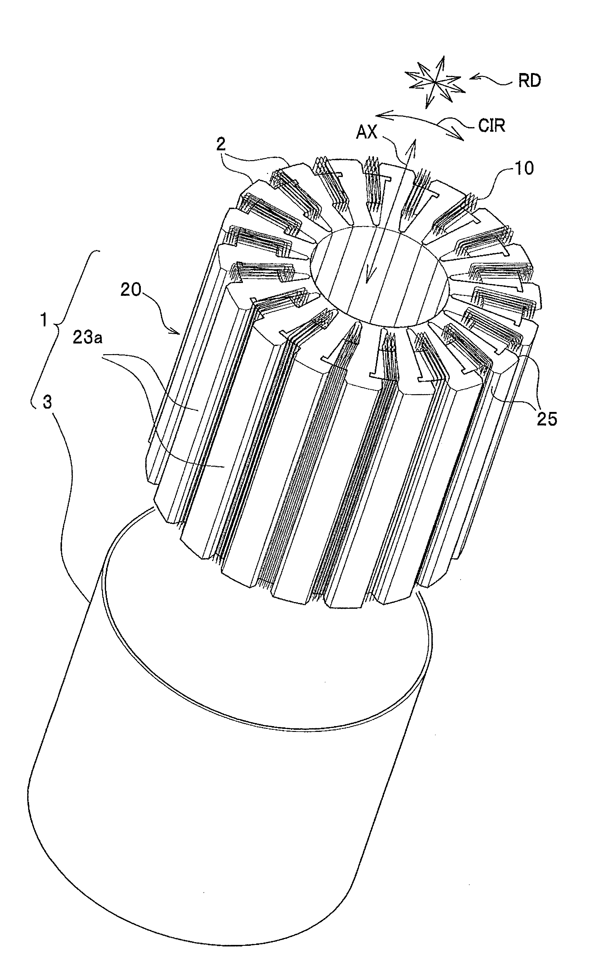
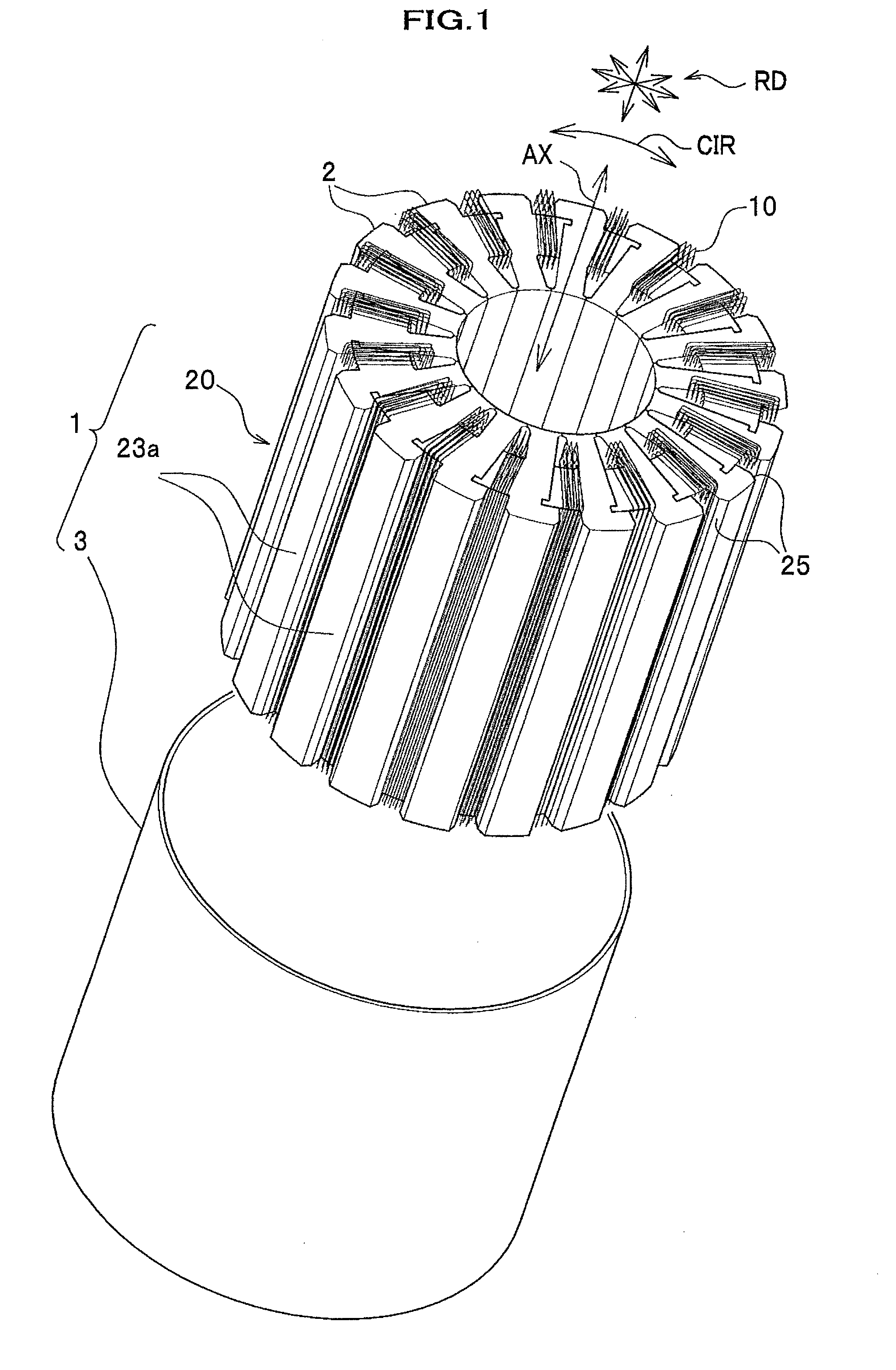
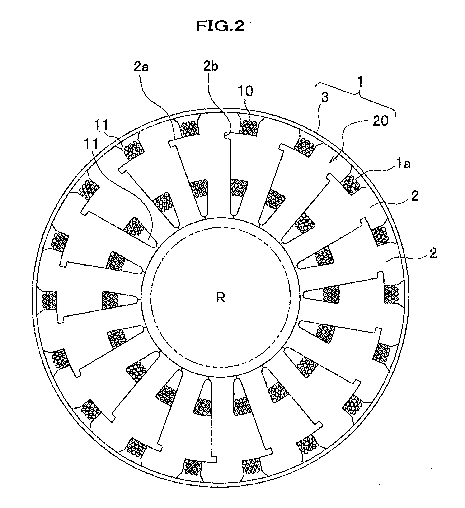
[0040]FIG. 1 is an exploded perspective view of the stator for the electrical rotating machine according to first and second embodiments of the present invention, and FIG. 2 is a sectional view of an electrical rotating machine including the stator for the electrical rotating machine according to the first and second embodiments of the present invention.

[0041]FIG. 3A is a perspective view of a divided core shown in a status where a stator winding is wound on a divided core 2. FIG. 3B is a sectional view of the divided core 2 shown in FIG. 3A. FIGS. 3C and 3D are partial sectional views of the divided cores having different shapes of the notches.

[0042]FIG. 4A is a perspective view of the divided core according to the first and second embodiments for showing a configuration of the divided core. FIG. 4B is a plan view of the divided core 2 shown in FIG. 4A.

[0043]The electrical rotating machine according to the embodiment of the present invention can be used as, for example, a motor (no...

second embodiment

[0065]Referring mainly to FIGS. 6A and 6B, will be described the stator for an electrical rotating machine according to a second embodiment. FIG. 6A is a perspective view of divided cores 2′ according to the second embodiment and FIG. 6B is a partial sectional view of the stator 1 for illustrating an operation of the divided cores.

[0066]The divided core 2′ according to the second embodiment is similar to the divided core 2 according to the first embodiment and is used as replacement of the divided core 2 in the stator 1. Thus, different points in the divided cores 2′ will be mainly described.

[0067]The divided cores 2′ according to the second embodiment of the present invention is a laminated member in which a plurality of electric steel plates made of a magnetic material are laminated and integrated by welding at two points at each of the connection part 23′ and the tooth 24′.

[0068]More specifically, at the connection part 23′ welding is made at welds 25a′ across a thickness of the ...


PUM


Abstract

A stator includes: a plurality of divided cores disposed to have a ring shape; a stator winding troidally wound on the stator; and a holding member that holds the divided cores in the ring shape. Each of the divided cores includes: a bobbin part for the stator winding; a yoke extending from the bobbin part in the circumferential direction; a connection part extending from the yoke outwardly in a radial direction with a connection face that is connected to the holding member; and a tooth extending from the yoke inwardly. The connection part has a magnetic gap to increase a magnetic resistance in a path of magnetic flux, generated by the stator winding, leaked to the holding member through the connection face. The magnetic gap is a notch or a weld.

Description

CROSS REFERENCE TO RELATED APPLICATIONS[0001]This application claims the foreign priority benefit under Title 35, United States Code, §119(a)-(d) of Japanese Patent Application No. 2008-234932, filed on Sep. 12, 2008 in the Japan Patent Office, the disclosure of which is herein incorporated by reference in its entirety.BACKGROUND OF THE INVENTION[0002]1. Field of the Invention[0003]The present invention relates to a stator for an electrical rotating machine and particularly to a stator for an electrical rotating machine including a holding member for holding a plurality of divided cores disposed in a circumferential direction in a ring.[0004]2. Description of the Related Art[0005]A stator for an electrical rotating machine, in which a winding is troidally wound for thinning and down-sizing of the electrical rotating motor, is known.[0006]JP 2006-271161A discloses a stator having divided cores and three parts protruded outwardly are provided with equi-angular intervals to reduce magn...

Claims


Application Information

Patent Timeline
Patent Type & Authority Applications(United States)
IPC IPC(8): H02K1/16
CPCH02K1/148
Inventor SHINAGAWA, MASATAKANAKAMURA, KIMIAKI
Owner HONDA MOTOR CO LTD
Why Eureka
Try Eureka