Magnetic recording disk drive with rotational vibration compensation having adaptive optimization of vibration sensor gains

a technology of rotational vibration compensation and vibration sensor gain, which is applied in the direction of magnetic recording, data recording, instruments, etc., can solve the problems of disturbance, disk drive rotational vibration and disturbance force, and the manufacturing cost of disk drive and the component cost of linear vibration sensor and circuit board can be significantly increased

Inactive Publication Date: 2010-03-18
WESTERN DIGITAL TECH INC
View PDF6 Cites 18 Cited by
  • Summary
  • Abstract
  • Description
  • Claims
  • Application Information

AI Technical Summary

Benefits of technology

[0010]The invention relates to a disk drive and a method for operating the disk drive that compensates for rotational vibration (RV) by adaptively modifying the gains of two separate vibration sensors so the sensor gains are optimal under any given condition. The disk drive includes two linear accelerometers that provide two signals S1, S2, respectively, to the disk drive's servo control processor. The processor uses S1, S2 and the position error signal (PES) as inputs to run an adaptive RV feedforward (RVFF) algorithm. The adaptive RVFF algorithm takes the

Problems solved by technology

Disk drives experience rotational vibration and disturbance forces during normal operation.
These disturbances arise internally, such as from motion of the VCM actuator, as well as externally, such as from shocks to the frame supporting the disk drive or from the movement of other disk drives when the drives are mounted together in a disk array system.
Thus the manufacturing cost of the disk drive and the component costs of t

Method used


Image

  • Magnetic recording disk drive with rotational vibration compensation having adaptive optimization of vibration sensor gains
  • Magnetic recording disk drive with rotational vibration compensation having adaptive optimization of vibration sensor gains
  • Magnetic recording disk drive with rotational vibration compensation having adaptive optimization of vibration sensor gains

Examples


Embodiment Construction

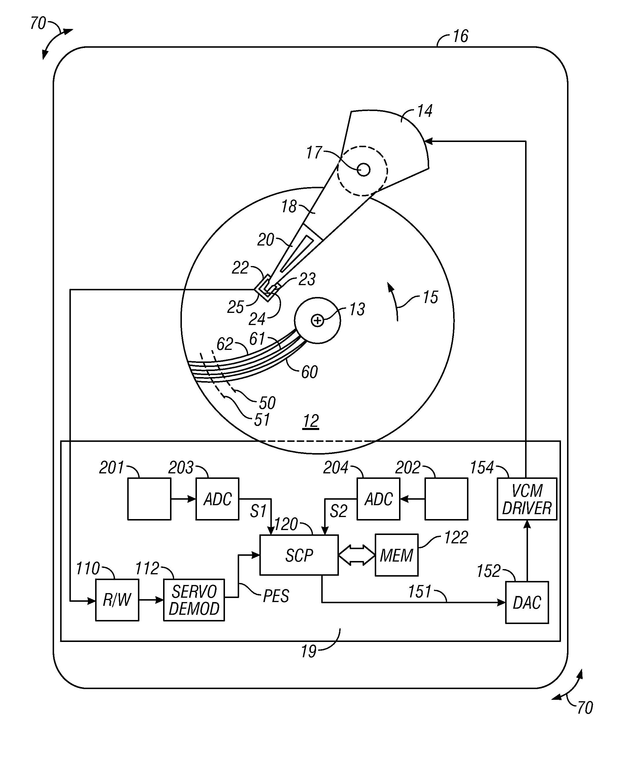
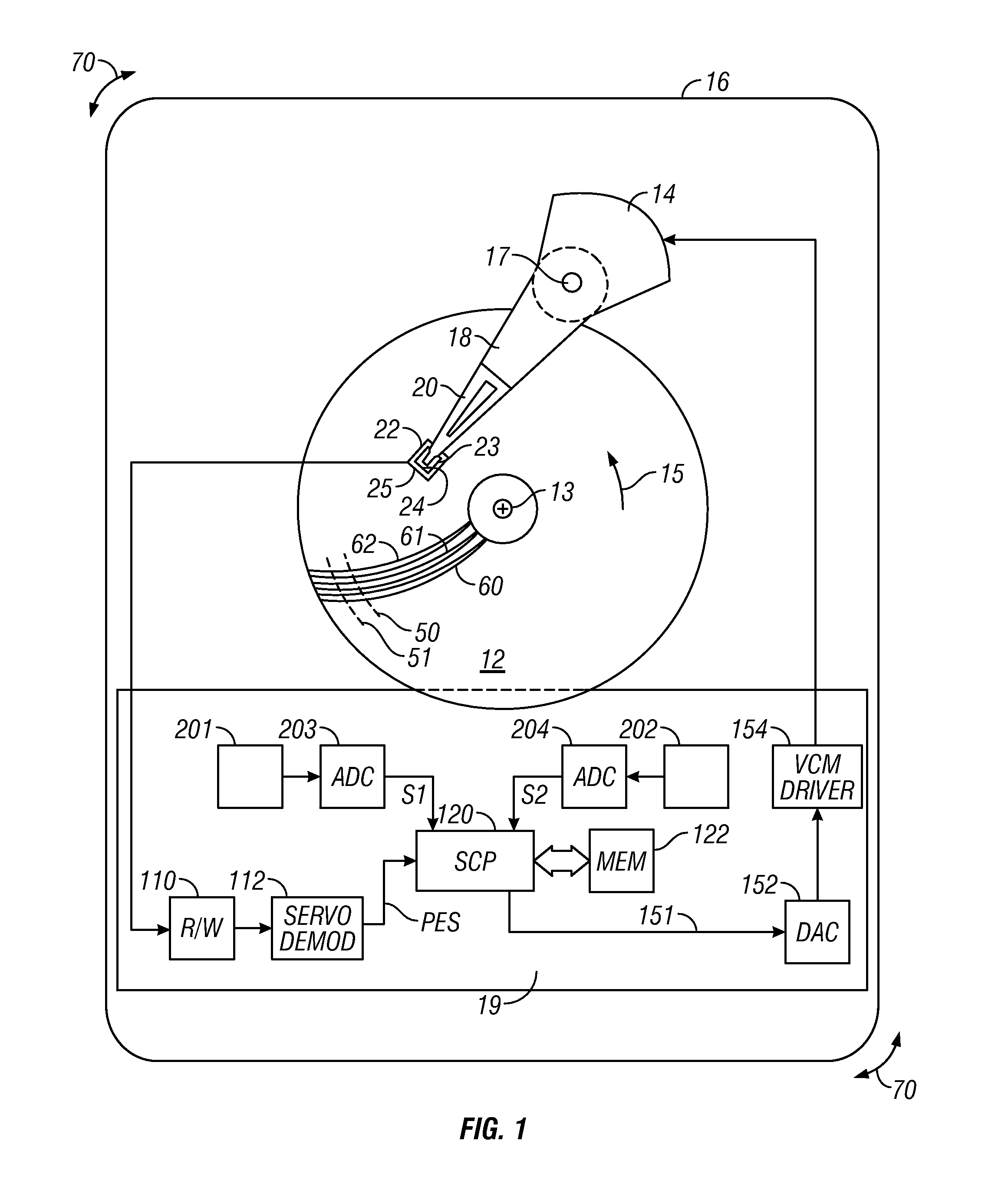
[0016]FIG. 1 is a block diagram of a magnetic recording hard disk drive according to the invention. The disk drive includes a magnetic recording disk 12 that is rotated about an axis of rotation 13 in direction 15 by a spindle motor (not shown) mounted to the disk drive housing or base 16. A printed circuit board 19 is attached to housing 16 and supports the disk drive electronics. The disk 12 has a magnetic recording layer patterned into magnetizable blocks that define concentric data tracks, such as typical tracks 50, 51, and servo sectors, such as typical servo sectors 60, 61, 62. The servo sectors extend generally radially across the concentric data tracks so that each data track has a plurality of equally-angularly spaced servo sectors that extend around the track. Each of the servo sectors in a data track typically contains a servo timing mark (STM) that indicates the start of the servo sector, a track identification (TID) code, and a portion of a pattern of magnetized blocks ...


PUM


Abstract

A disk drive and a method for operating the disk drive compensates for rotational vibration (RV) by adaptively modifying the gains of two separate linear vibration sensors so the sensor gains are optimal under any given condition. The two sensors provide two signals S1, S2, respectively, to the disk drive's servo control processor that generates the control signal to the voice coil motor (VCM) actuator that controls the positioning of the read/write head. The processor uses S1, S2 and the head position error signal (PES) as inputs to run an adaptive RV feedforward (RVFF) algorithm. The adaptive RVFF algorithm takes the PES and sensor outputs S1 and S2 as inputs, mathematically determines the required correction to the sensor gain factors k1 and k2, respectively, and then adjusts the gain factors k1 and k2 accordingly. Each signal S1, S2 is then modified by its adjusted gain factor k1, k2, respectively. The difference in the modified S1, S2 signals is the RVFF signal that is summed with the control signal to generate the RV-compensated control signal to the VCM actuator.

Description

BACKGROUND OF THE INVENTION[0001]1. Field of the Invention[0002]This invention relates generally to magnetic recording disk drives, and more particularly to a disk drive that includes a system for canceling the effects of rotational vibration.[0003]2. Description of the Related Art[0004]Magnetic recording hard disk drives use an actuator, typically a rotary voice-coil-motor (VCM) actuator, for positioning the read / write heads on the data tracks of the recording disks. The disk drive has a servo control system that receives a position error signal (PES) from servo positioning information read by the heads from the data tracks and generates a VCM control signal to maintain the heads on track and move them to the desired track for reading and writing of data.[0005]Disk drives experience rotational vibration and disturbance forces during normal operation. These disturbances arise internally, such as from motion of the VCM actuator, as well as externally, such as from shocks to the frame...

Claims


Application Information

Patent Timeline
IPC IPC(8): G11B17/00
CPCG11B5/59627G11B5/5582
Inventor HUANG, FU-YINGSEMBA, TETSUOSUN, XIAOTIAN
Owner WESTERN DIGITAL TECH INC
Why Eureka
Try Eureka