Communication System and Method For Wirelessly Exchanging User Data With a User Terminal

a communication system and user terminal technology, applied in the field of wireless communication systems, can solve the problems of increased data transmission capacity of the uu interface, data connection of wireless access stations, and inability of intermediate stations to communicate with user terminals, so as to avoid signal delay and improve interference conditions

Inactive Publication Date: 2010-03-18
KONINK KPN NV +1
View PDF14 Cites 12 Cited by
  • Summary
  • Abstract
  • Description
  • Claims
  • Application Information

AI Technical Summary

Benefits of technology

[0032]By providing the direct interconnection between the first and second wireless access station, other information, such as handover data, may also be transmitted over the interconnection in another embodiment. The direct interconnection may also avoid signal delay as compared to the situation wherein signals should be transferred indirectly between the wireless access stations via the RNC or other controller.
[0033]In order for a wireless direct interconnection to achieve an appropriate bit rate, it is not desirable for the distance between the wireless access stations to exceed a distance as set forth in an embodiment. As described previously, an intermediate station may be provided to allow the distance between Node-Bs to increase and to improve the interference conditions.

Problems solved by technology

Therefore, the increased data transmission capacity for the Uu interface may encounter a bottleneck at the Iub interface as a result of the restricted data transfer capacity for the data connections of the Node-Bs.
However, the above problem for the data connections of wireless access stations are also encountered for such communication systems.
The intermediate station may or may not be able to communicate with user terminals.

Method used


Image

  • Communication System and Method For Wirelessly Exchanging User Data With a User Terminal
  • Communication System and Method For Wirelessly Exchanging User Data With a User Terminal
  • Communication System and Method For Wirelessly Exchanging User Data With a User Terminal

Examples


Embodiment Construction

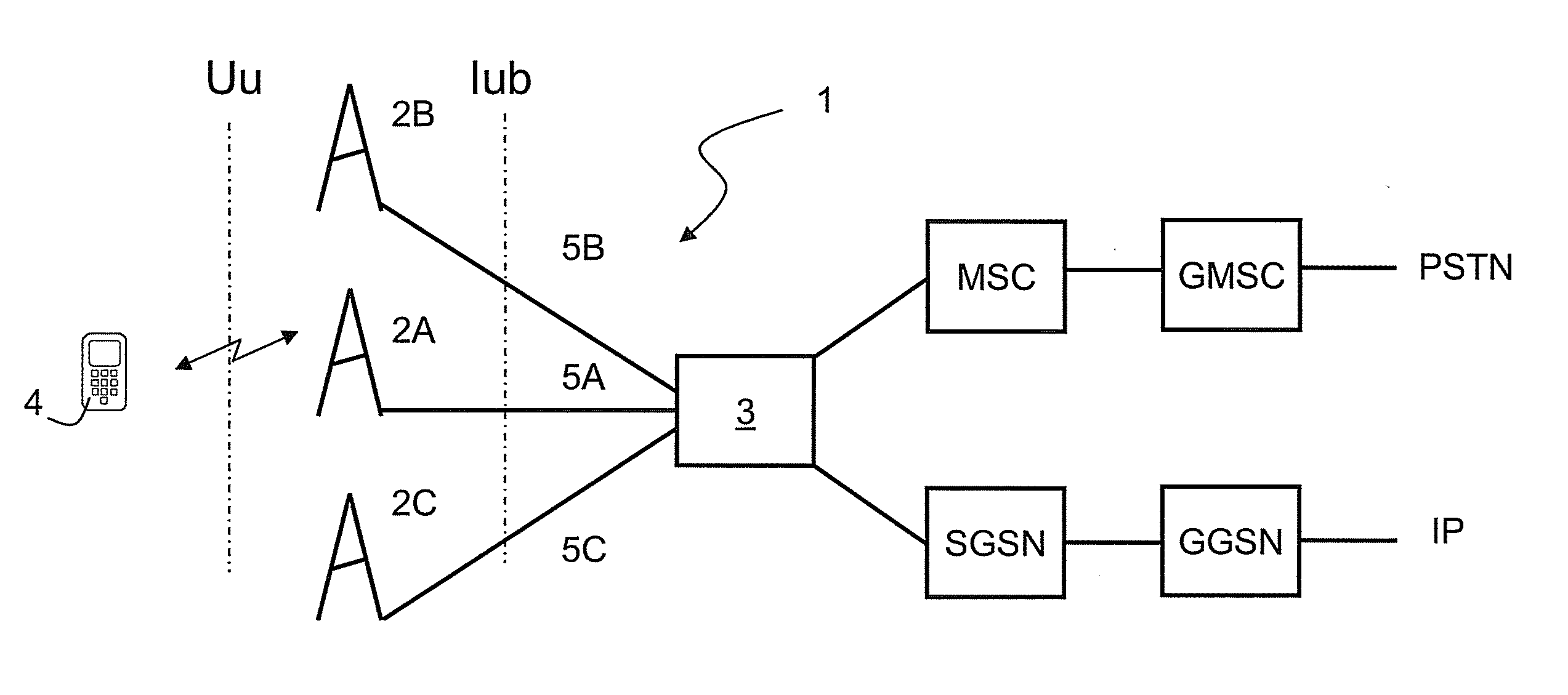
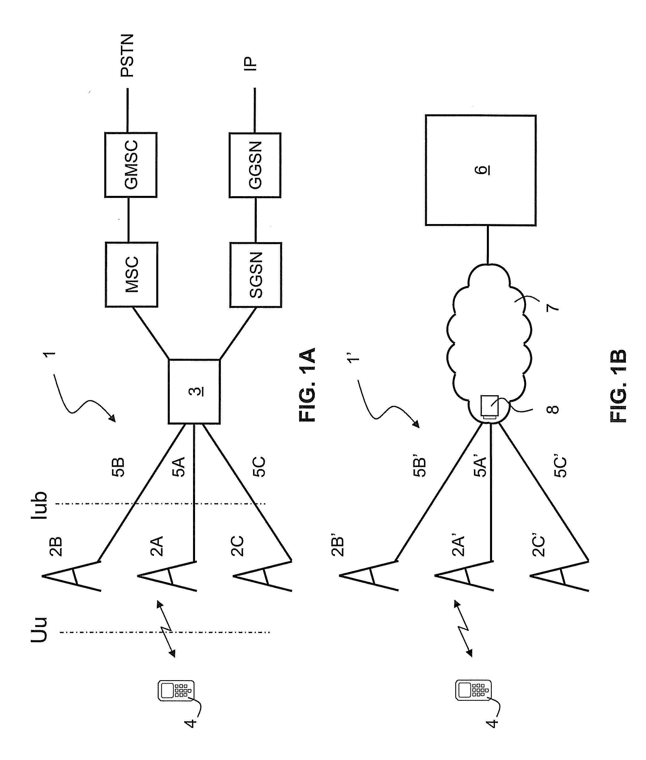
[0040]FIG. 1A is a schematic illustration of a UMTS communication system 1. UMTS communication system 1 comprises a radio access network having a plurality of wireless access stations 2A, 2B, 2C and a radio network controller 3. Below, the wireless access stations 2A-2C are referred to as Node-Bs, whereas controller 3 is abbreviated as RNC (radio network controller) for the system of FIG. 1A.

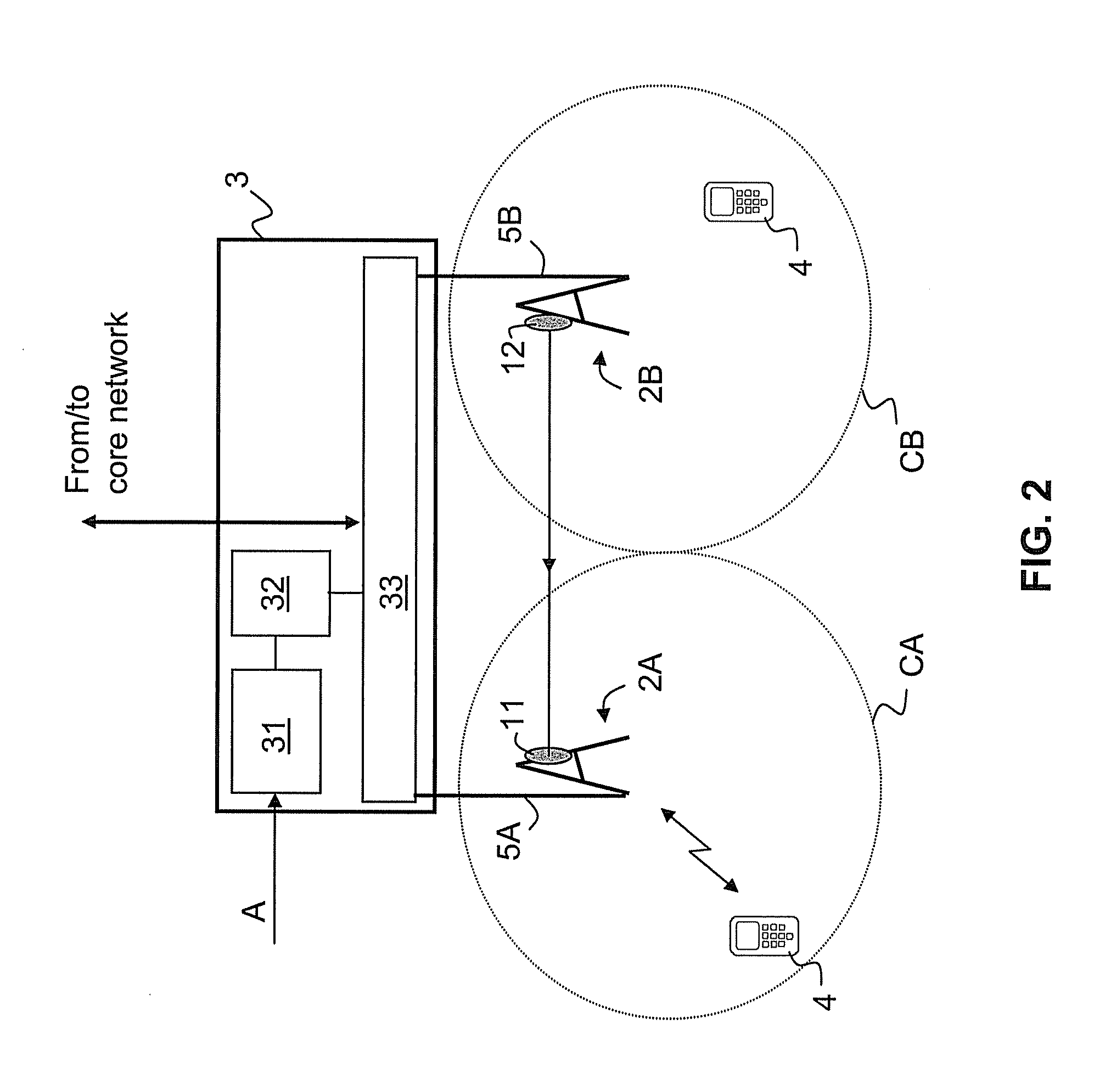
[0041]The Node-Bs 2A-2C provide wireless access for a user terminal 4 (also referred to as user equipment UE) by defining and supporting one or more cells (see FIG. 2). The radio interface between the UE 4 and Node-B 2A is referred to as the Uu-interface.

[0042]Each Node-B 2A-2C has a corresponding data connection 5A-5C to the RNC 3 of the radio access network. The interface between a Node-B and the RNC is referred to as the Iub interface. The data connection 5A-5C may comprise one or more connections (wired and / or wireless) with a constrained data transmission capacity. Data transport over the I...


PUM


Abstract

The invention relates to a communication system including a first wireless access station with a first data connection for transferring user data and a second wireless access station with a second data connection for transferring user data. The first wireless access station and second wireless access station are located at distant positions from each other. The first wireless access station has one or more antennas for wirelessly transmitting user data that are received over the first data connection to a user terminal. The second wireless access station is configured to receive user data over the second data connection and to transmit the user data directly to the first wireless access station for transmission to the user terminal. The communication system further includes a controller configured for controlling at least a part of the user data for the user terminal to flow over the second data connection.

Description

CROSS-REFERENCE TO RELATED APPLICATIONS[0001]The present application claims priority to European Patent Application EP 08016082.3 filed in the EPO Patent Office on Sep. 12, 2008, the entire contents of which is incorporated herein by reference.FIELD OF THE INVENTION[0002]The invention relates to the field of wireless communication systems. In particular, the invention relates to a communication system and method of wirelessly exchanging user data with a user terminal.DESCRIPTION OF THE RELATED ART[0003]Wireless communication systems enable wireless exchange of user data between a wireless access station (also referred to as base station) and a user terminal. The user terminal may be a mobile user terminal accessing the wireless communication system for receiving user data from and transmitting user data to the base station.[0004]Wireless communication systems typically comprise a radio access network and a core network. For UMTS communication systems, details are provided in 3GGP 23...

Claims


Application Information

Patent Timeline
Patent Type & Authority Applications(United States)
IPC IPC(8): H04W4/00
CPCH04W92/20H04L47/14H04W28/0247H04W28/08H04W28/02H04W8/04
Inventor VAN DER WAL, JACOB CORNELISGUSTAFSSON, NILS ANDERS STEFANJORGUSESKI, LJUPCO
Owner KONINK KPN NV
Why Eureka
Try Eureka