Optical component for euvl and smoothing method thereof

Inactive Publication Date: 2010-03-18
ASAHI GLASS CO LTD
View PDF2 Cites 20 Cited by
  • Summary
  • Abstract
  • Description
  • Claims
  • Application Information

AI Technical Summary

Benefits of technology

[0050]According to the smoothing method of the present invention, it is possible to smooth the optical surface having the concave defects while minimizing the decrease in flatness and the deterioration in surface roughness, by irradiating the optical surface of the optical component for EUVL having the concave defects with a laser having an o

Problems solved by technology

However, since there is no material capable of transmitting light therethrough in the EUV light energy region, a refractive optical system cannot be used.
If minute irregularities are present on the optical surface of an optical component for EUVL, this adversely affects the reflective multilayer and absorber layer formed on the optical surface.
For example, if minute irregularities are present on the optical surface, the periodic structure of the reflective multilayer film formed on the optical surface is disturbed and when EUVL is performed using a mask or mirror for EUVL produced using the optical component for EUVL, the desired pattern may be partially lost or an extra pattern other than the desired pattern may be formed.
The disorde

Method used


Image

  • Optical component for euvl and smoothing method thereof
  • Optical component for euvl and smoothing method thereof

Examples


example

[0121]The present invention is described further in more detail based on examples, but the present invention is not limited to these examples. In addition, Examples 9 to 13 are examples and Examples 1 to 8 are reference examples.

example i

Irradiation Example I

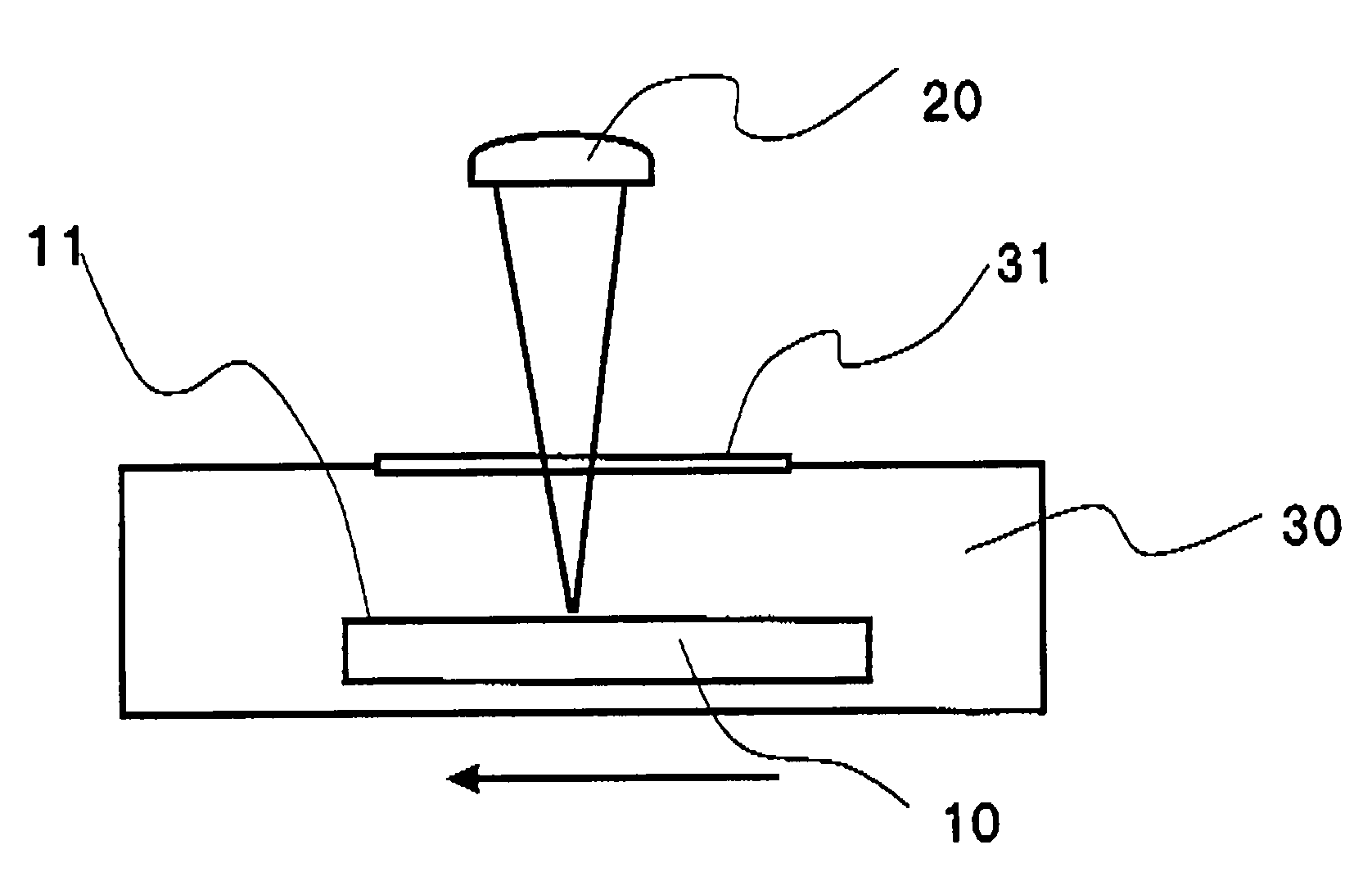
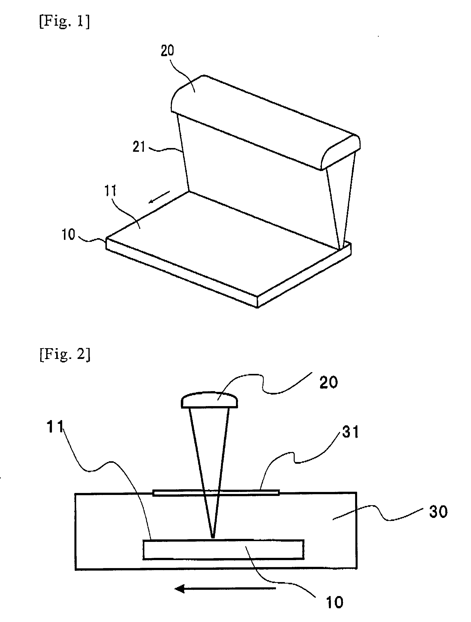
[0122]The entire surface of a substrate obtained by cutting a silica glass substrate containing TiO2 as a dopant (having a TiO2 concentration of 7.0 mass %) (Product No. AZ6025 manufactured by Aschi Glass Company, Ltd. of 150 mm square) into a size of 5 cm square was irradiated with a KrF excimer laser (LPX305 manufactured by Coherent Ltd. having a pulse width of 25 ns) while changing an irradiation fluence and the number of shots. At this time, the atmosphere around the substrate is an air with the relative humidity of 60% (water vapor partial pressure of 14.3 mmHg) at a room temperature of 25° C. The KrF excimer laser applied to the substrate surface was in the form of a line beam (25 mm×0.55 mm) using a cylindrical lens as an irradiation optical system and the entire substrate surface was irradiated with the KrF excimer laser by scanningly moving the substrate surface with respect to the line beam.

[0123]The number of shots means the number of times of irradia...

example ii

Irradiation Example II

[0129]Plural concave defects existing in the optical surface of a silica glass substrate containing TiO2 as a dopant (having a TiO2 concentration of 7.0 mass %) (Product No. AZ6025 manufactured by Asahi Glass Company, Ltd. of 150 mm square) were detected and the size (depth) thereof and the RMS value around the concave defects were measured. Scanning irradiation was carried out with respect to plural areas of 20 mm square including the concave defects, with the KrF excimer laser in the form of a line beam, in the same manner as in the above-mentioned examples.

[0130]In Example 1 and Examples 4 to 6, the laser irradiation was carried out in the air with the relative humidity of 60% (water vapor partial pressure of 14.3 mmHg) at a room temperature of 25° C. In Examples 11 to 13, the laser irradiation was carried out while spraying the laser irradiating site on the substrate surface with a nitrogen gas having a purity of 99.99% using a nozzle.

[0131]The irradiation ...


PUM

PropertyMeasurementUnit
Temperatureaaaaaaaaaa
Fractionaaaaaaaaaa
Timeaaaaaaaaaa

Abstract

The present invention provides a method for smoothing an optical surface of an optical component for EUVL. Specifically, the present invention provides a method for smoothing an optical surface of an optical component for EUVL made of a silica glass material containing TiO2 and comprising SiO2 as a main component with a laser having an oscillation wavelength, to which the optical component for EUVL has an absorption coefficient of 0.01 μm−1 or more, at a fluence of 0.3 to 1.5 J/cm2 in an atmosphere having a water vapor partial pressure of 3.6 mmHg or less.

Description

TECHNICAL FIELD[0001]The present invention relates to a method for smoothing an optical component for EUV lithography (hereinafter referred to as “EUVL”). More specifically, the present invention relates to a method for smoothing the optical surface having a concave defect such as pit or scratch of an optical component for EUVL (hereinafter referred to as “the smoothing method of the present invention”).[0002]Also, the present invention relates to an optical component for EUVL obtained by the smoothing method of the present invention.BACKGROUND ART[0003]In the lithography technology, an exposure tool for manufacturing an integrated circuit by transferring a minute circuit pattern onto a wafer has hitherto been widely utilized. With the trend toward a higher degree of integration and a higher function of an integrated circuit, the refinement of the integrated circuit is advancing. The exposure tool is hence required to form a circuit pattern image with high resolution on a wafer surf...

Claims


Application Information

Patent Timeline
IPC IPC(8): G03F1/00B29D11/00G02B1/12G02B5/08G03F1/24G03F1/60
CPCB82Y10/00B82Y40/00C03C23/0025G21K2201/067G03F1/14G03F1/24G03F1/60C03C2204/08H01L21/0275G03F1/86G03F1/62
Inventor ONO, MOTOSHIWATANABE, MITSURUYOKOYAMA, MIKA
Owner ASAHI GLASS CO LTD
Why Eureka
Try Eureka