Power unit

a technology of power unit and power transmission path, which is applied in the direction of locomotive transmission, electric motor propulsion transmission, gearing, etc., can solve the problems of reducing the manufacturing cost of the vehicle, inhibiting the reduction of weight or downsizing, and auxiliary devices not being able to drive by the engine, so as to simplify the configuration of the first power transmission path

Inactive Publication Date: 2010-03-25
HONDA MOTOR CO LTD
View PDF3 Cites 17 Cited by
  • Summary
  • Abstract
  • Description
  • Claims
  • Application Information

AI Technical Summary

Benefits of technology

[0044]The provision of the function of the second locking mechanism to the forward/reverse rotation switching mechanism enables a reduction...

Problems solved by technology

During the stop of engine operation, however, the auxiliary devices are not able to be driven by the engine.
Therefore, th...

Method used


Image

  • Power unit
  • Power unit
  • Power unit

Examples


first embodiment

[0064]A first embodiment of the present invention will be described with reference to FIGS. 1 to 12.

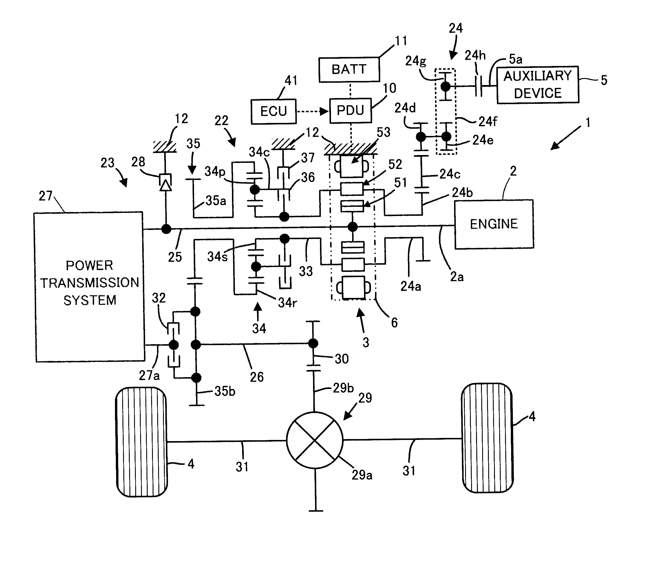
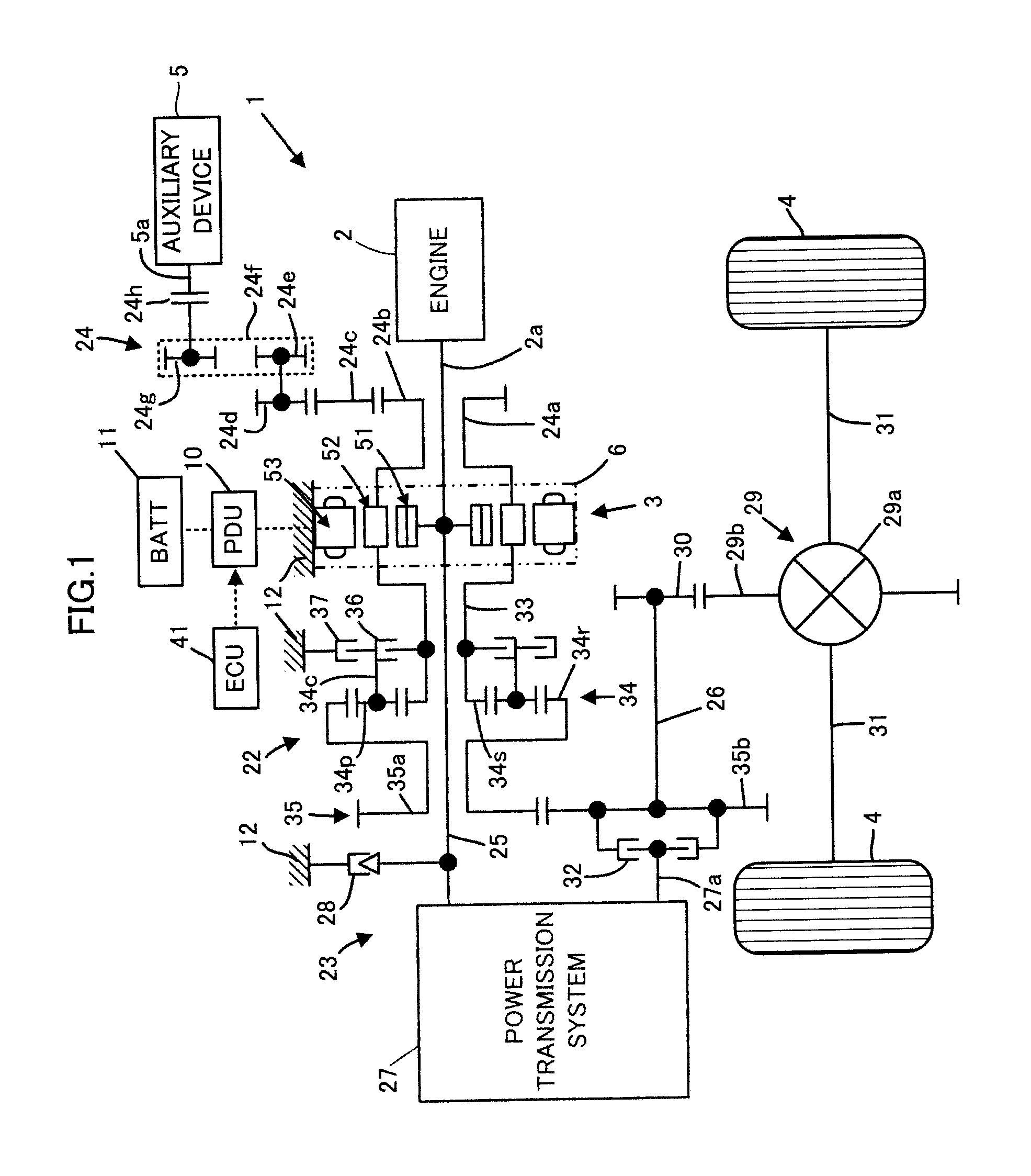
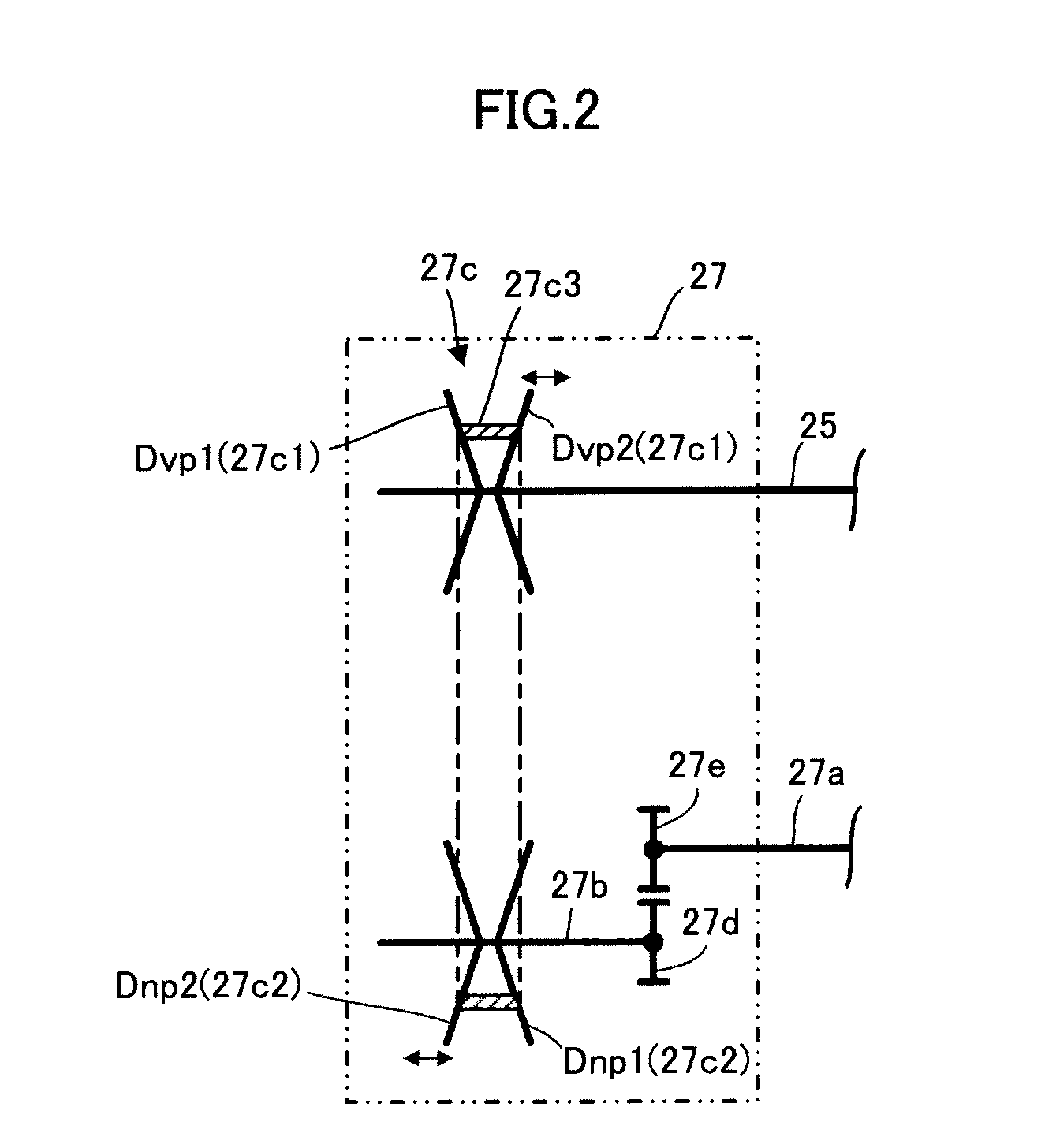
[0065]First, referring to FIGS. 1 and 2, the configuration of a power unit 1 according to this embodiment will be described.

[0066]Referring to FIG. 1, the power unit 1 according to this embodiment is a power unit mounted on a hybrid vehicle, having an engine 2 and a rotating machine 3 as power generation sources. Further, the power unit 1 is adapted to be capable of driving a pair of driving wheels 4, 4 by transmitting power of the engine 2 or the rotating machine 3 to the driving wheels 4, 4. In addition, the power unit 1 is adapted to be capable of driving an auxiliary device 5 mounted on the vehicle by transmitting the power of the engine 2 or the rotating machine 3 to the auxiliary device 5 as well as the driving wheels 4, 4. The auxiliary device 5 is, for example, an air conditioner compressor, a water pump, an oil pump, or the like.

[0067]In this embodiment, the engine 2 and the ...

second embodiment

[0209]The following describes a second embodiment of the present invention with reference to FIGS. 13 to 14. This embodiment is different from the power unit 1 of the first embodiment only in a part of the configuration of the rotating machine. More specifically, this embodiment includes a rotating machine 60 which is different from the rotating machine 3 only in a part of the configuration (the rotating machine 60 which functions as an energy dispensing / synthesizing system in the fourth invention), instead of the rotating machine 3. Therefore, in the description of this embodiment, the same components as those in the first embodiment are denoted by the same reference numerals as in the first embodiment and their description is omitted.

[0210]Referring to FIG. 13, the rotating machine 60 includes a first rotor 61 and a second rotor 62 as two bodies of rotation rotationally supported in a housing 64 of the rotating machine 60 and includes an immovable stator 63 fixed to the housing 64...

third embodiment

[0236]The following describes a third embodiment of the present invention with reference to FIGS. 15 to 17. This embodiment is different from the power unit 1 of the first embodiment only in a part of the configuration of the rotating machine. More specifically, this embodiment includes a rotating machine 70 which is different from the rotating machine 3 only in a part of the configuration (the rotating machine 70 which functions as an energy dispensing / synthesizing system in the fourth invention), instead of the rotating machine 3. Therefore, in the description of this embodiment, the same components as those in the first embodiment are denoted by the same reference numerals as in the first embodiment and their description is omitted.

[0237]While the power unit of the second embodiment includes the rotating machine 60 having two rotating machine structures, the rotating machine 70 of this embodiment has still more rotating machine structures such as, for example, three rotating mach...


PUM


Abstract

A power unit includes: an energy dispensing/synthesizing system in which a first body of rotation is connected to an output shaft of a prime mover and a second body of rotation is connected to a driven unit via a first power transmission path; a first power transmission system selectively operable between an operating state for enabling power transmission in the first power transmission path and an operating state for disconnecting the power transmission; a second power transmission path connecting between the output shaft of the prime mover and the driven unit; and a second power transmission system selectively operable between an operating state for enabling power transmission in the second power transmission path and an operating state for disconnecting the power transmission, wherein an auxiliary device is connected to a second body of rotation of the energy dispensing/synthesizing system.

Description

BACKGROUND OF THE INVENTION[0001]1. Field of the Invention[0002]The present invention relates to a power unit for driving a driven unit such as wheels of a vehicle.[0003]2. Description of the Related Art[0004]For example, as a vehicle, which runs by transmitting engine power to driving wheels as a driven unit, there has conventionally been known a vehicle which automatically stops engine operation during a stop at an intersection (so-called an idle-stop vehicle) as described in Japanese Patent Application Laid-Open No. 2003-269212 (hereinafter, referred to as Patent Document 1).[0005]On the other hand, a vehicle generally includes various auxiliary devices such as a water pump, an air conditioner compressor, and a power steering pump. In this case, these auxiliary devices are able to be driven by using the engine power during engine operation. During the stop of engine operation, however, the auxiliary devices are not able to be driven by the engine.[0006]Therefore, in the case of t...

Claims


Application Information

Patent Timeline
IPC IPC(8): B60W20/00H02K1/00B60L11/14B60L50/16
CPCB60K6/26B60K6/365B60K6/448B60K6/547B60K2006/262B60W10/06Y02T10/6286B60W20/00B60W2710/0644F16H2037/102H02K51/00Y02T10/6243B60W10/08Y02T10/62B60K2006/268B60W20/30B60W10/10B60W2710/10
Inventor AKUTSU, SHIGEMITSUABE, NORIYUKI
Owner HONDA MOTOR CO LTD
Why Eureka
Try Eureka