Concurrent monitoring of a plurality of samples by an array of biosensing elements

a biosensing element and array technology, applied in the field of sensing techniques, can solve the problems of complex series of reactions that can only exist in an intact, functioning cell, molecular recognition or chemical analysis can rarely provide this type of information, and achieve the effect of improving the detectivity of the respons

Inactive Publication Date: 2010-03-25
YISSUM RES DEV CO OF THE HEBREWUNIVERSITY OF JERUSALEM LTD
View PDF6 Cites 15 Cited by
  • Summary
  • Abstract
  • Description
  • Claims
  • Application Information

AI Technical Summary

Benefits of technology

[0036]a detection unit comprising a single receiving element associated with said array of biosensing elements and configured for concurrently receiving the multiple response signals and generating a single output signal indicative thereof;
[0037]The system thereby enabling to identify, in said single output signal, signal parts corresponding to the response signals of the spatially separated biosensing elements, based on the different frequencies in the response signals coming from the different sites.
[0038]In preferred embodiments of the invention, the exciting signals are pulsed signals, and different tagging frequencies are pulsing frequencies of the exciting pulses.
[0042]The system thereby enabling to identify, in said single output signal, signal parts corresponding to the response signals of the spatially separated biosensing elements, based on the different pulsing frequencies of the response signal

Problems solved by technology

This triggers very complex series of reactions that can exist only in an intact, functioning

Method used


Image

  • Concurrent monitoring of a plurality of samples by an array of biosensing elements
  • Concurrent monitoring of a plurality of samples by an array of biosensing elements
  • Concurrent monitoring of a plurality of samples by an array of biosensing elements

Examples


Embodiment Construction

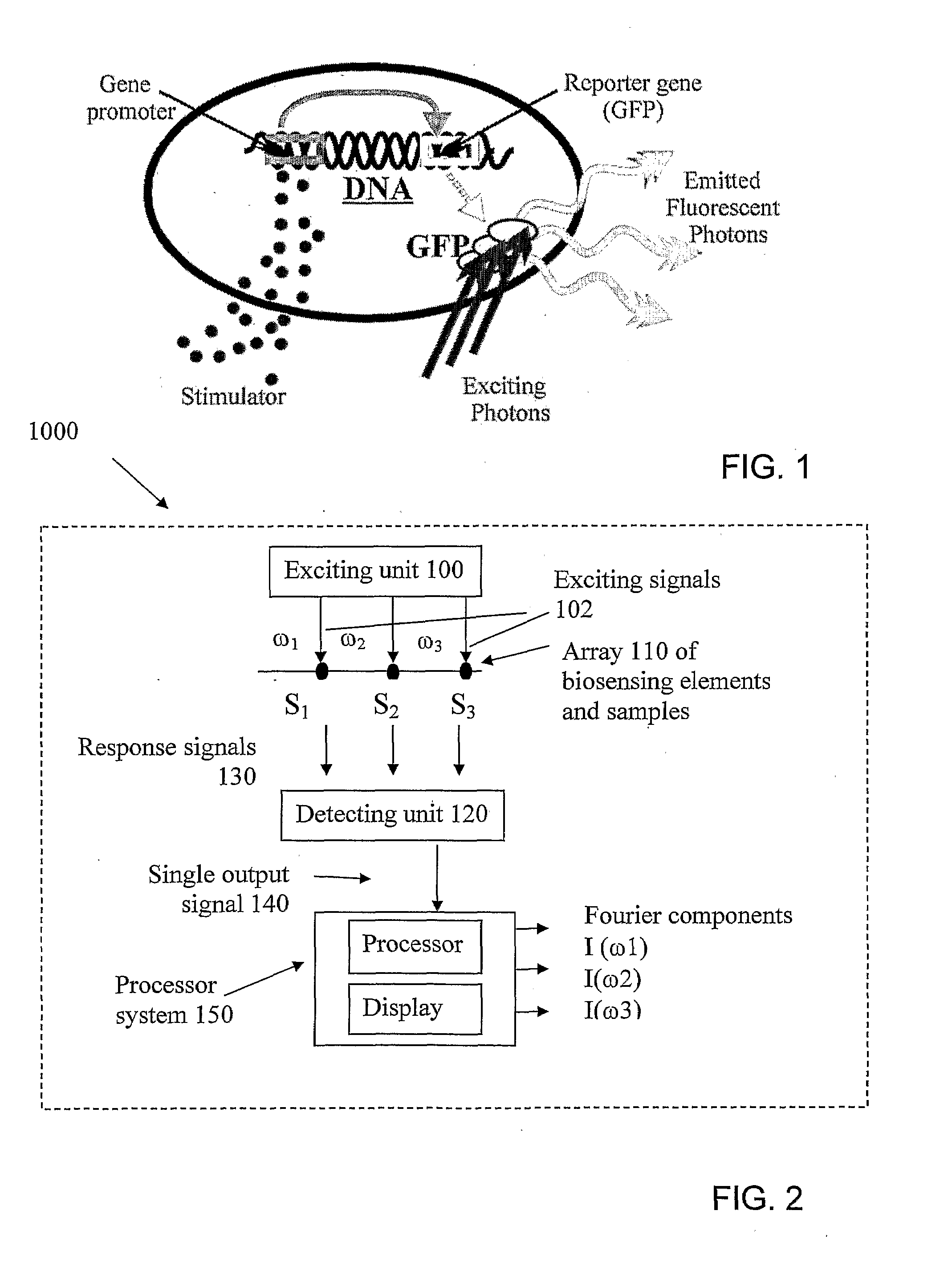
[0074]FIG. 1 illustrates general principles of identifying a sample by its interaction with a microbial biosensing element, that might result in the production of a fluorescent molecule signifying the presence of the target element. Applying exciting light to the biosensor allows for detecting the fluorescence if any, and thus identifying the sample and / or the target agent.

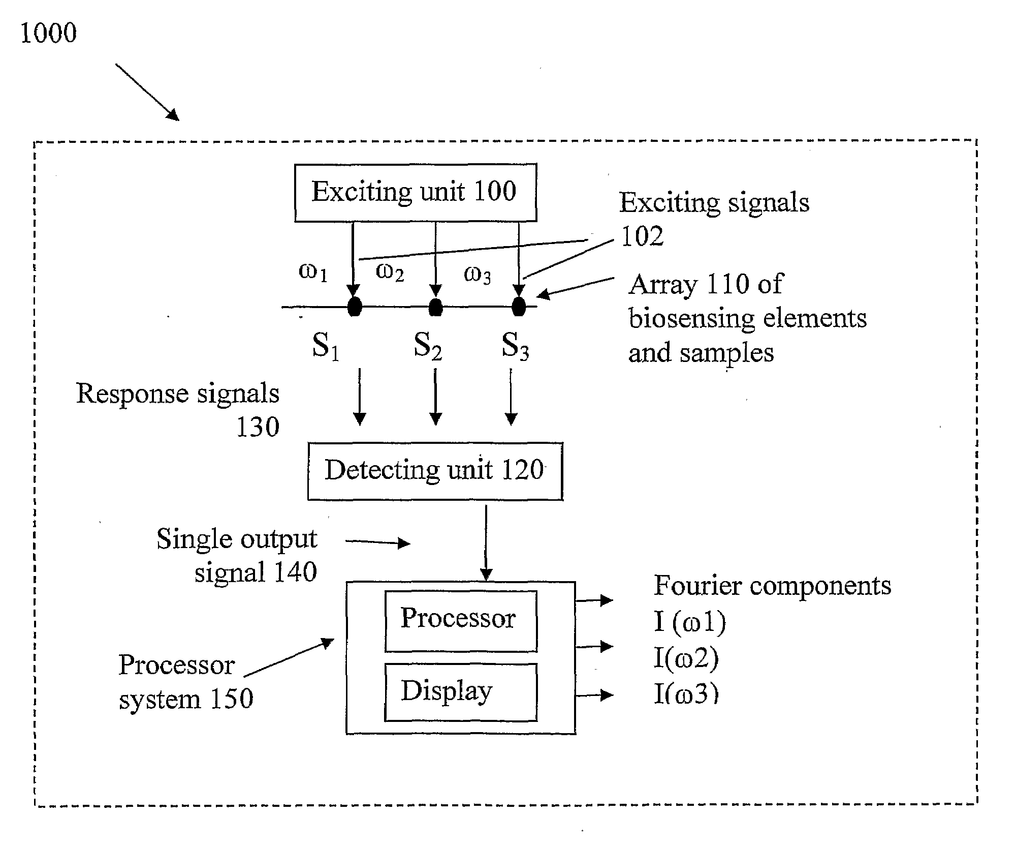
[0075]The present invention takes advantages of the above technique, and provides a novel method and system enabling concurrent monitoring of multiple samples while interacting with multiple biosensing elements.

[0076]More specifically, the present invention utilizes optical monitoring technique applied to biosensing elements of the kind responding by fluorescence, when a fluorescent molecule is created as a result of the biosensing element interaction with a sample, and is therefore described below with respect to this specific application. It should however be noted that the invention is not limited to this speci...


PUM

PropertyMeasurementUnit
Phaseaaaaaaaaaa
Frequencyaaaaaaaaaa
Wavelengthaaaaaaaaaa

Abstract

A system and method are presented for monitoring detectable responses from multiple biosensing elements while in contact with multiple samples located in an array. The system (1000) comprises an exciting unit (100), and a detection unit (120). The exciting unit (100) is configured for producing an array of exciting signals (102) each characterized by a frequency differing from those of the other exciting signals, and exciting a corresponding array of the biosensing elements (110), thereby enabling each biosensing element to generate a response signal (130) tagged by the different frequency. The detection unit (120) comprises a single receiving element associated with said array of biosensing elements (110) and configured for concurrently receiving the multiple response signals and generating a single output signal (140) indicative thereof. The system thereby enables to identify signal parts corresponding to the response signals of the spatially separated biosensing elements.

Description

FIELD OF THE INVENTION[0001]This invention is generally in the field of sensing techniques, and relates to a system and method for concurrent monitoring of a plurality of samples by an array of biosensing elements while in contact with the samples.REFERENCES[0002]The following references are considered to be pertinent for the purpose of understanding the background of the present invention:[0003]1. Belkin, S, 2003. Whole-cell environmental sensing of pollutants. Current Opinion Microbiol., 6: 206-212.[0004]2. Daunert, S., Barrett, G, Feliciano, J. S., Shetty, R. S., Shrestha, S. and Smith-Spencer W. 2000. Genetically engineered whole-cell sensing systems: coupling biological recognition with reporter genes. Chem. Rev. 100: 2705-2738.[0005]3. Kohler, S., S. Belkin and R. D. Schmid. 2000. Reporter gene bioassays in environmental analysis (review). Fresen. J. Anal. Chem. 366: 769-779[0006]4. Walmsley, R. M., N. Billinton and W. D. Heyer, 1997. Green fluorescent protein as a reporter fo...

Claims


Application Information

Patent Timeline
IPC IPC(8): G01N21/64C40B60/12C40B30/00C23C14/48
CPCG01N21/6428G01N2021/6484G01N21/6452
Inventor AGRANAT, AHARONBELKIN, SHIMSHON
Owner YISSUM RES DEV CO OF THE HEBREWUNIVERSITY OF JERUSALEM LTD
Why Eureka
Try Eureka