Ultra-compact, linear, solar-thermal steam generator

a solar thermal and generator technology, applied in the direction of solar heat generation, solar heat systems, lighting and heating apparatus, etc., can solve the problems of large field required for a given thermal output, less effective, and high convection heat loss of absorbers, so as to achieve the effect of optimizing their position

Inactive Publication Date: 2010-04-01
FEHER PETER
View PDF4 Cites 22 Cited by
  • Summary
  • Abstract
  • Description
  • Claims
  • Application Information

AI Technical Summary

Benefits of technology

[0006]The present application thus describes a “traveling” ultra-compact reflector field, where the reflector rows have a new, additional degree of freedom of horizontal mobility, perpendicular to the longitudinal axis of

Problems solved by technology

The Pro-Solar rows have typically less exposed normal surface, thus they are less effective.
The trade-off of such design is the higher convectional heat loss of the absorbers.
1) Large space requirement or limited reflector surface-to-ground surface ratio. This is typical for systems that are designed to minimize the overlapping-shadowing effect (blocking off either the incident or reflected sunlight) of adjacent reflectors. The distance between the reflector rows and their orientation may be optimized for a specific position of the Sun on the sky that occurs only once (twice for equinox) a year. In order to make the highest use of the reflector surfaces, the rows are spaced with considerable gaps between them. This way the extent of the field required for a given thermal output becomes large. Large field then results in extensive and costly piping and other service infrastructures.
2) Limited reflected energy per unit of linear length of the mirror. This is typical for systems that are designed to minimize the area of reflector field. In this case the reflector rows are often spaced evenly, close to each other. These systems have low reflector area utilization because the above described blocking-shadowing effect.
3) Limited seasonal energy. This is typical for all known systems, including the floating rotating “Solar-Island” concept. This disadvantage comes from the fixed position of the reflectors in relation to the collectors. This anchored position of the mirrors, even if it is optimized, it is ideal only for a single

Method used


Image

  • Ultra-compact, linear, solar-thermal steam generator
  • Ultra-compact, linear, solar-thermal steam generator
  • Ultra-compact, linear, solar-thermal steam generator

Examples


Embodiment Construction

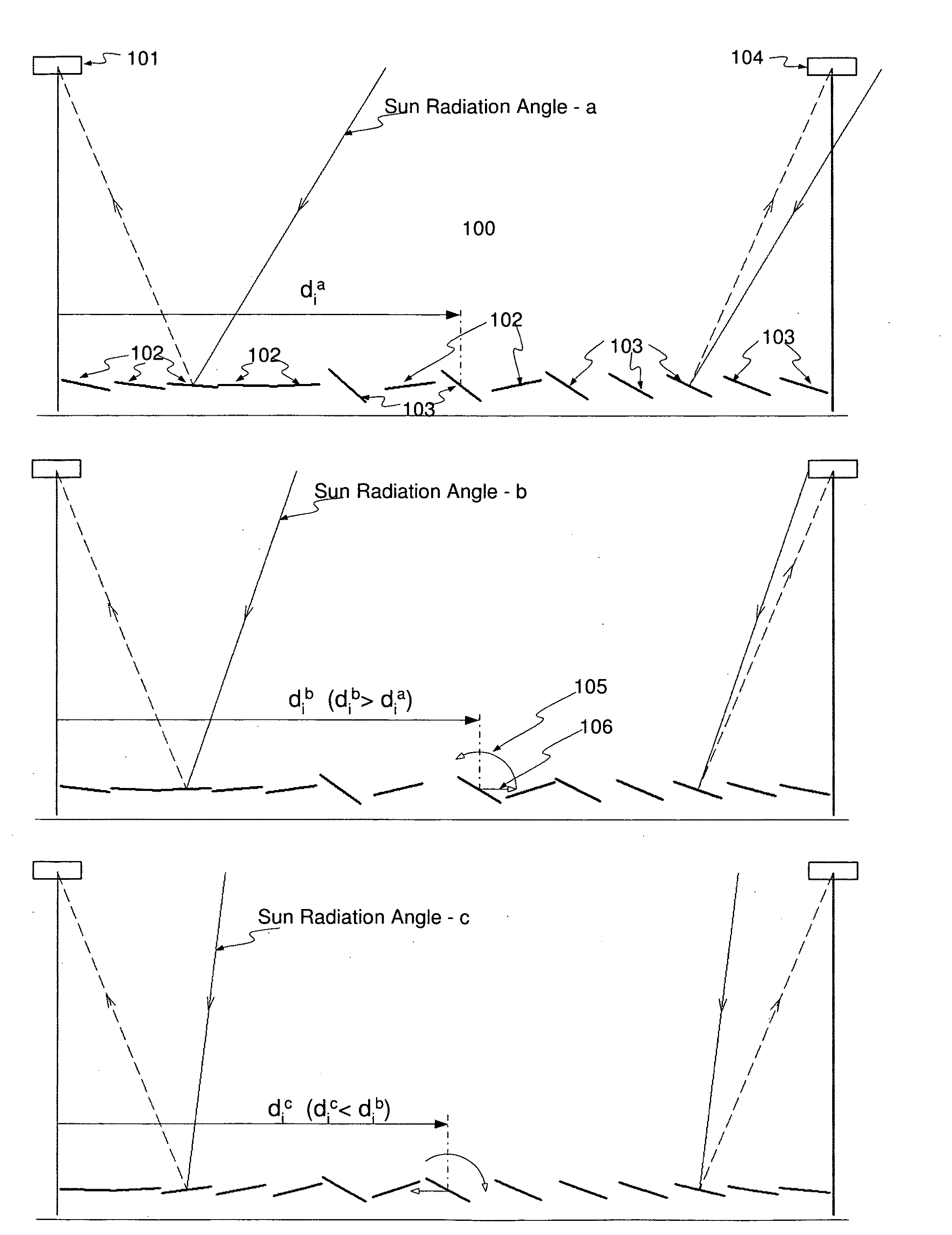
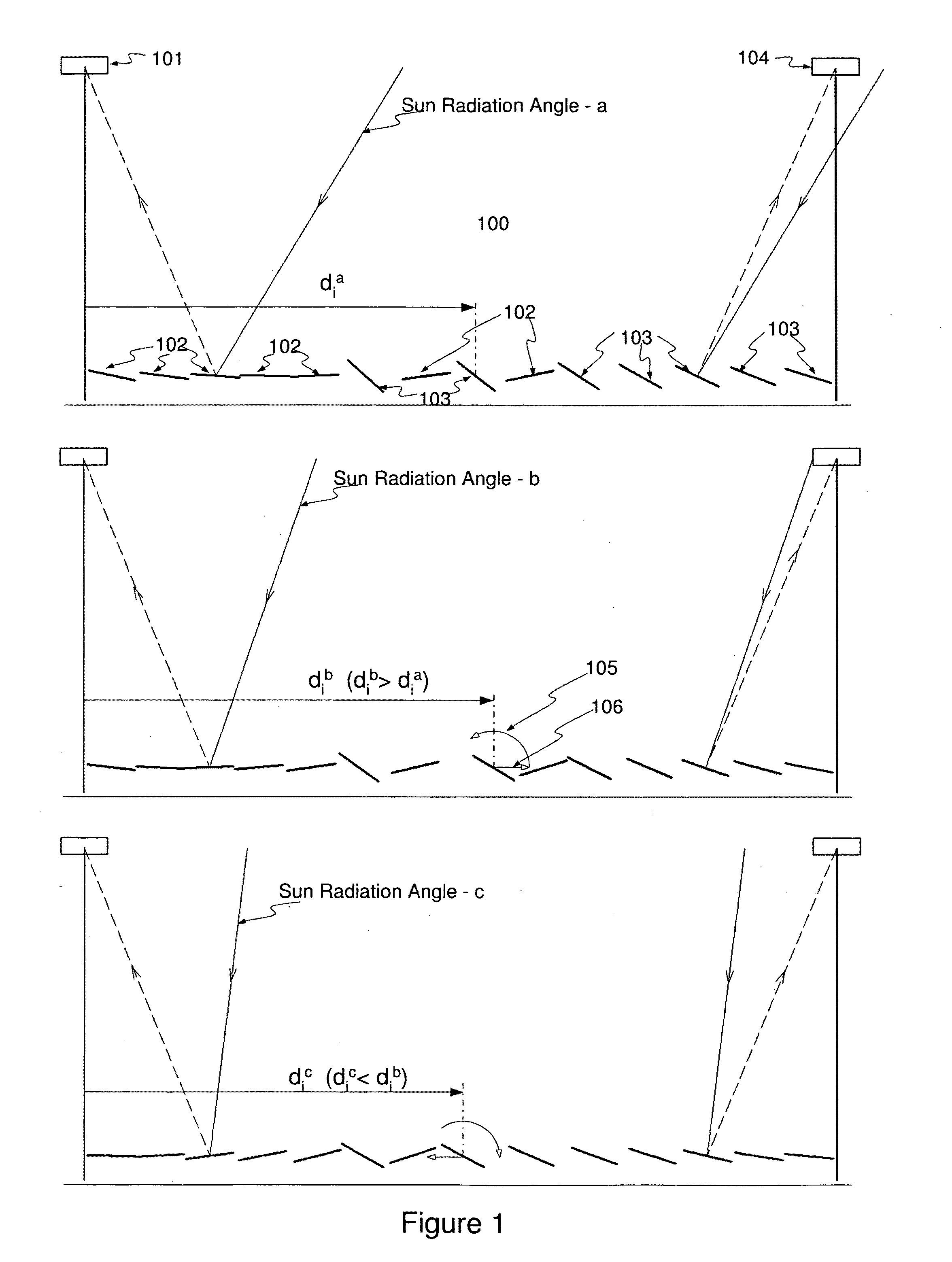
[0017]Referring now to the drawings, in which like numerals indicate like elements throughout the several views, FIG. 1 shows a schematic view of Basic Field Unit 100, comprised of multiple rows of reflectors 102 and 103, between two adjacent collectors 101 and 104 elevated on columns, located above the reflectors. A multitude of BFUs aligned parallel with the reflector rows, and connected to one common steam generation loop comprises one Steam Generation Module (SGM). Multitude of SGMs comprises the Solar Thermal Steam Generation (STSG) Field.

[0018]Based on optimization strategies, the reflectors may target either of the two collectors on the edges of the BFU. Pending on which side of the targeted collector the reflector is, compared to Sun's position; there are Pro-Solar 102 and Contra-Solar 103 reflectors. The Pro-Solar ones are on the same side of the collector as the Sun. The Contra-Solar ones are on the opposite side of the collector compared to the Sun. Similarly the collecto...


PUM


Abstract

Direct solar thermal steam generator with an ultra-compact linear Fresnel reflector field that has “travel and turn” capability by means of independent linear and rotational motion of reflectors.
Method of positioning and orienting the reflectors of the traveling field such that the reflected energy of the field is maximized at all times
Crescent like rotational support rail of the reflector with its gravitational center in the center of the crescent. The curvature of the reflector is customized for each row of the field
Ultra-light, collector-absorber structure, with cable suspended arch-like tubular absorber, wide aperture, and secondary reflector with optimized light entrapment
Flow distribution and control method of the large horizontal solar thermal steam generation field.

Description

TECHNICAL FIELD[0001]The present application relates generally to solar thermal energy collectors and more particularly relates to direct solar thermal steam generation.BACKGROUND OF THE INVENTION[0002]The type of solar thermal collectors referred as “Linear Fresnel Reflectors” (LFR) are known and used for their simplicity and cost effectiveness. These are fields of flat or quasi-flat reflector “strips” (long and narrow bands) arranged in parallel rows and oriented to a common collector located at a certain height above the reflector field. The collector is also a strip-like, long and narrow structure, aligned in parallel with the rows of reflectors designed to collect the energy from the reflector field. One collector collects the reflected energy from multiple reflector rows on each of its sides. For discussion purposes the basic unit of the field is defined as two adjacent collectors and the reflectors between them. In theory any reflector can serve either of the two collectors. ...

Claims


Application Information

Patent Timeline
IPC IPC(8): F24J2/10F24J2/38F24S23/70F24S50/20
CPCF22B1/006F24J2/07F24J2/10F24J2/5406F24J2002/1014Y02E10/47F24J2002/5437F24J2002/5458F24J2002/5475F24J2002/5479Y02E10/41F24J2002/108F24S20/20F24S23/70F24S30/422F24S2023/832F24S2023/872F24S2030/11F24S2030/133F24S2030/14F24S2030/145Y02E10/40
Inventor FEHER, PETER
Owner FEHER PETER
Why Eureka
Try Eureka