Floating baffle panel and filter apparatus

a filter apparatus and baffle panel technology, applied in the direction of liquid displacement, sewage draining, separation process, etc., can solve the problems of large influence of friction between water and media, poor removal efficiency of fine particles, and low efficiency of hydrodynamic separators

Active Publication Date: 2010-04-01
OLDCASTLE INFRASTRUCTURE INC
View PDF15 Cites 21 Cited by
  • Summary
  • Abstract
  • Description
  • Claims
  • Application Information

AI Technical Summary

Benefits of technology

[0008]The present invention is a storm water filter system for filtering floatable debris and non-floating pollutants from storm water passing through a storm water drain system vault. The storm water filtering system has a vault having chamber having a wall between the inlet thereto and the outlet therefrom. The wall has a filter passageway therethrough for filtering the storm water and a floatable baffle panel covering a second passageway therethrough for capturing floatable debris and trash from the storm water. Storm water entering the vault inlet passes through a filter element and out the outlet and also can pass under the floating baffle panel when the floatable baffle panel is floated to a raised position to thereby prevent storm water from accumulating on the inlet side of the wall.
[0009]The storm water filter system has a vault housing having a chamber therein having an inlet thereinto and an outlet therefrom and a wall mounted therein between the inlet and the outlet. The wall has a filter opening therethrough and a filter element removably mounted therein for filtering storm water passing therethrough. A pair of tracks are attached to the wall and define a passageway therethrough for movably supporting a floating baffle

Problems solved by technology

Hydrodynamic separators do very little to remove the dissolved pollutants and have a typically poor removal efficiency for fine particles.
However, a problem with using filter media in a storm water treatment system is the significant influence of friction between the water and the media.
In addition, changing the directi

Method used


Image

  • Floating baffle panel and filter apparatus
  • Floating baffle panel and filter apparatus
  • Floating baffle panel and filter apparatus

Examples


Embodiment Construction

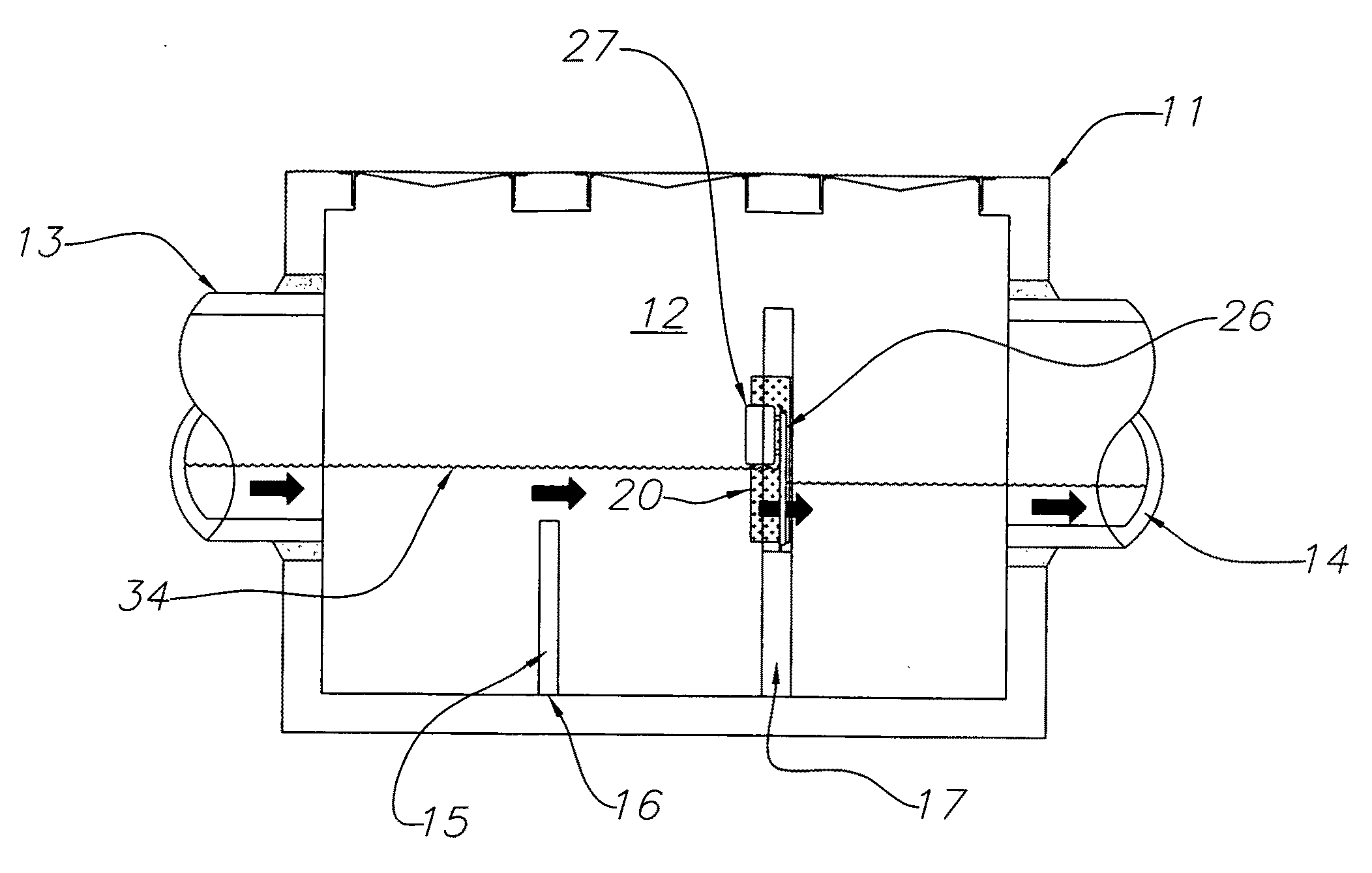
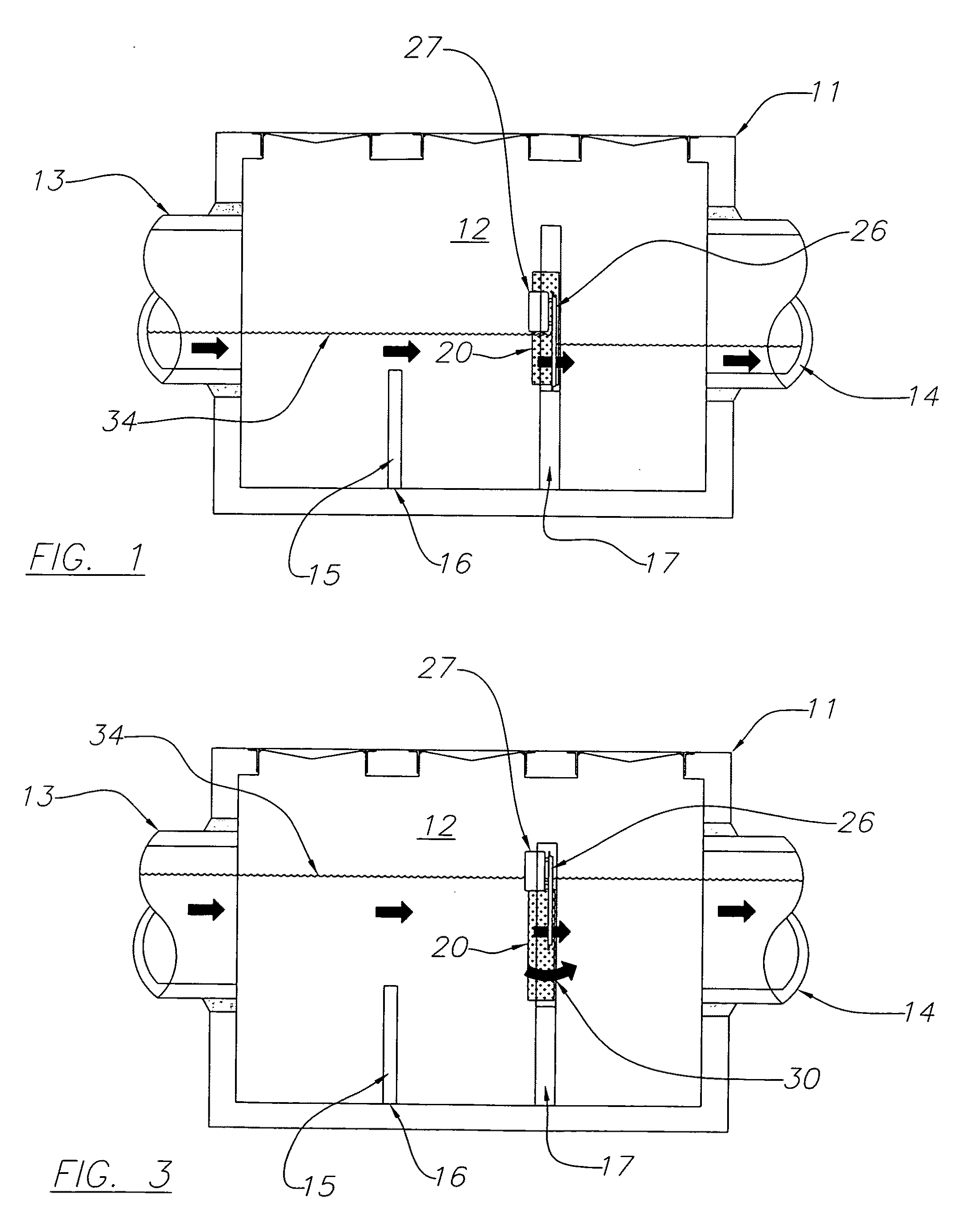
[0018]Referring to the drawings, FIGS. 1 through 7, and especially to FIGS. 1 through 5 a filtering system 10 has a vault 11 having a chamber 12 therein and an inlet 13 and an outlet 14. The vault has a baffle 15 extending from the base 16 thereof. A filtering and baffle wall 17 is mounted in the vault 11 chamber 12.

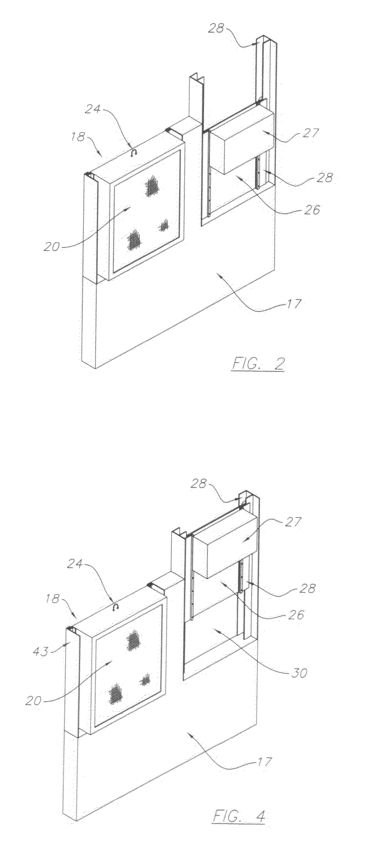
[0019]The wall 17 has a filter opening 18 therethrough sized for a filter element 20. The filter element 20 is removably mounted in the opening 18 with side edges 21 sliding in channel tracks 22. A bottom channel 23 receives a bottom edge 23 of the filter 20 to seal the filter into the opening 18. The filter element 20 has a gripping member 24 for gripping the filter 20 during removal and replacement of filters.

[0020]A wide variety of filter media is readily available in the market place. The selection of the desired filter media is typically determined by targeting treatment with regard to the pollutants of concern. The filter media of the present filter can have multip...


PUM

PropertyMeasurementUnit
Forceaaaaaaaaaa

Abstract

The present invention is a storm water filter system for filtering floatable debris and non-floating pollutants from storm water passing through a storm water drain system vault. The storm water filtering system has a vault having chamber having a wall between the inlet thereto and the outlet therefrom. The wall has a filter passageway therethrough for filtering the storm water and a floatable baffle panel covering a second passageway therethrough for capturing floatable debris and trash from the storm water. Storm water entering the vault inlet passes through a filter element and out the outlet and also can pass under the floating baffle panel when the floatable baffle panel is floated to a raised position to thereby prevent storm water from accumulating on the inlet side of the wall.

Description

[0001]This patent application is a continuation-in-part application of my pending U.S. patent application Ser. No. 12 / 587,574, filed Oct. 13, 2009 for a Floating Skimmer with Up-Flow Filter; which is Continuation-in-part of my pending U.S. patent application Ser. No. 12 / 387,583, filed May 6, 2009 for a Storm Water Filter System Having a Floating Skimmer Apparatus; which is a continuation-in-part of my pending U.S. patent application Ser. No. 12 / 315,820, filed Dec. 8, 2008 for a Storm Water Filter System Having a Floating Skimmer Apparatus; which is based on my U.S. Provisional patent application Ser. No. 61 / 009,086, filed Dec. 27, 2007 for a Floating Skimmer Apparatus. The present invention is a storm water filter system for filtering floatable debris and non-floating pollutants from storm water passing through a storm water drain system and more specifically, the present invention is directed towards a storm water filtering system having a floatable baffle panel therein for capturi...

Claims


Application Information

Patent Timeline
IPC IPC(8): B01D35/02C02F1/00E03F1/00B01D29/05B01D35/14
CPCB01D21/0003B01D21/0012B01D21/0027B01D21/0042E03F5/14B01D2221/12C02F1/004C02F2103/001B01D21/2438Y02A20/152
Inventor HAPPEL, THOMAS H.
Owner OLDCASTLE INFRASTRUCTURE INC
Why Eureka
Try Eureka