Robust Stereo Calibration System and Method for Accurate Digital Image Correlation Measurements
a stereo calibration and digital image technology, applied in the field of robust stereo calibration systems and methods for accurate can solve the problems of reducing the accuracy of digital image correlation measurements, sacrificing any accuracy, and increasing the cost more rapidly
- Summary
- Abstract
- Description
- Claims
- Application Information
AI Technical Summary
Benefits of technology
Problems solved by technology
Method used
Image
Examples
example 1
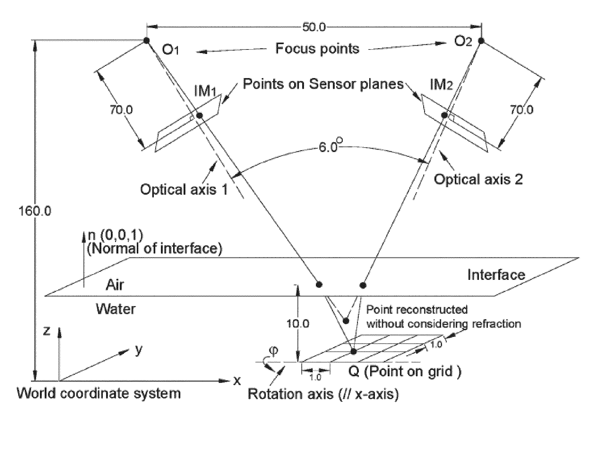
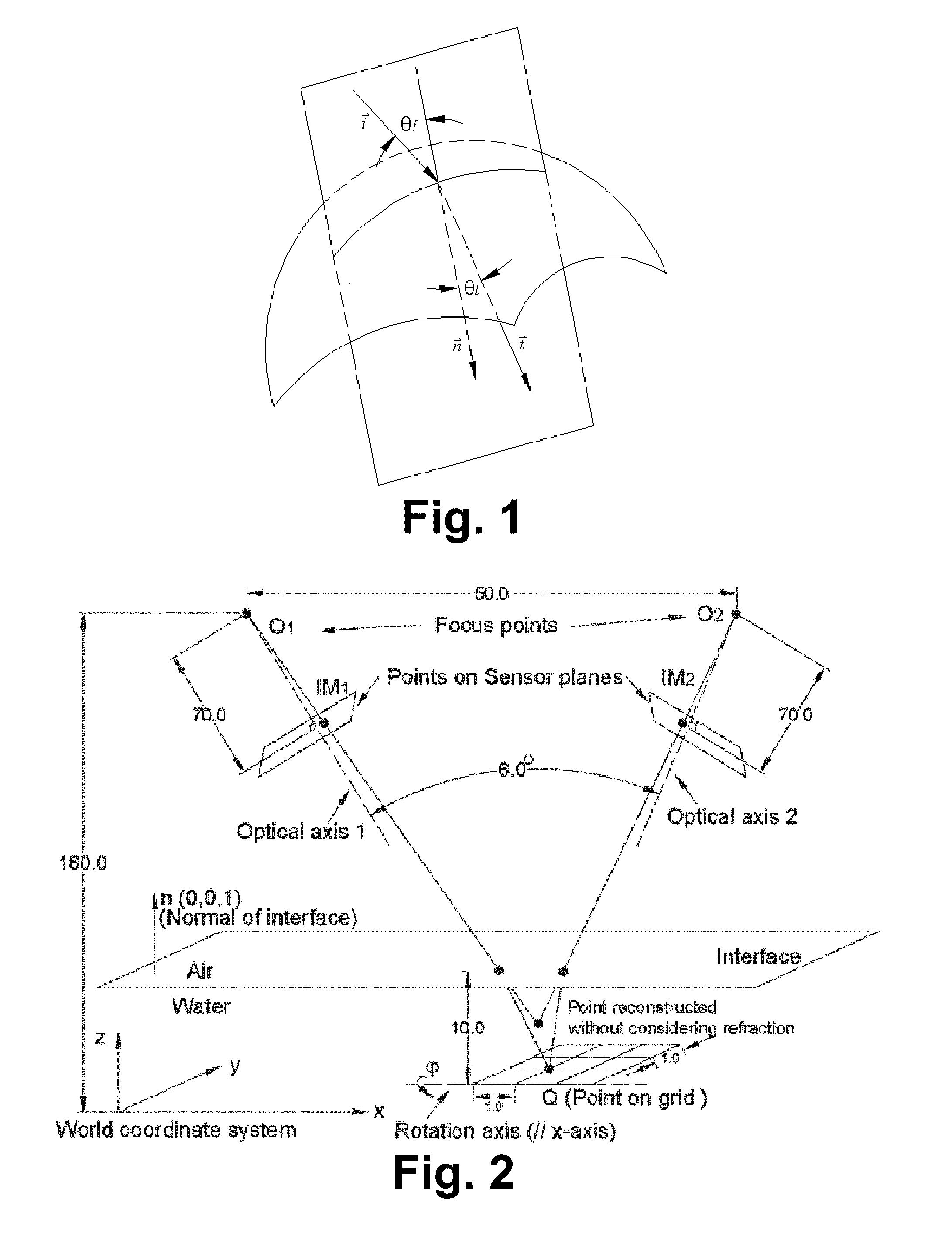
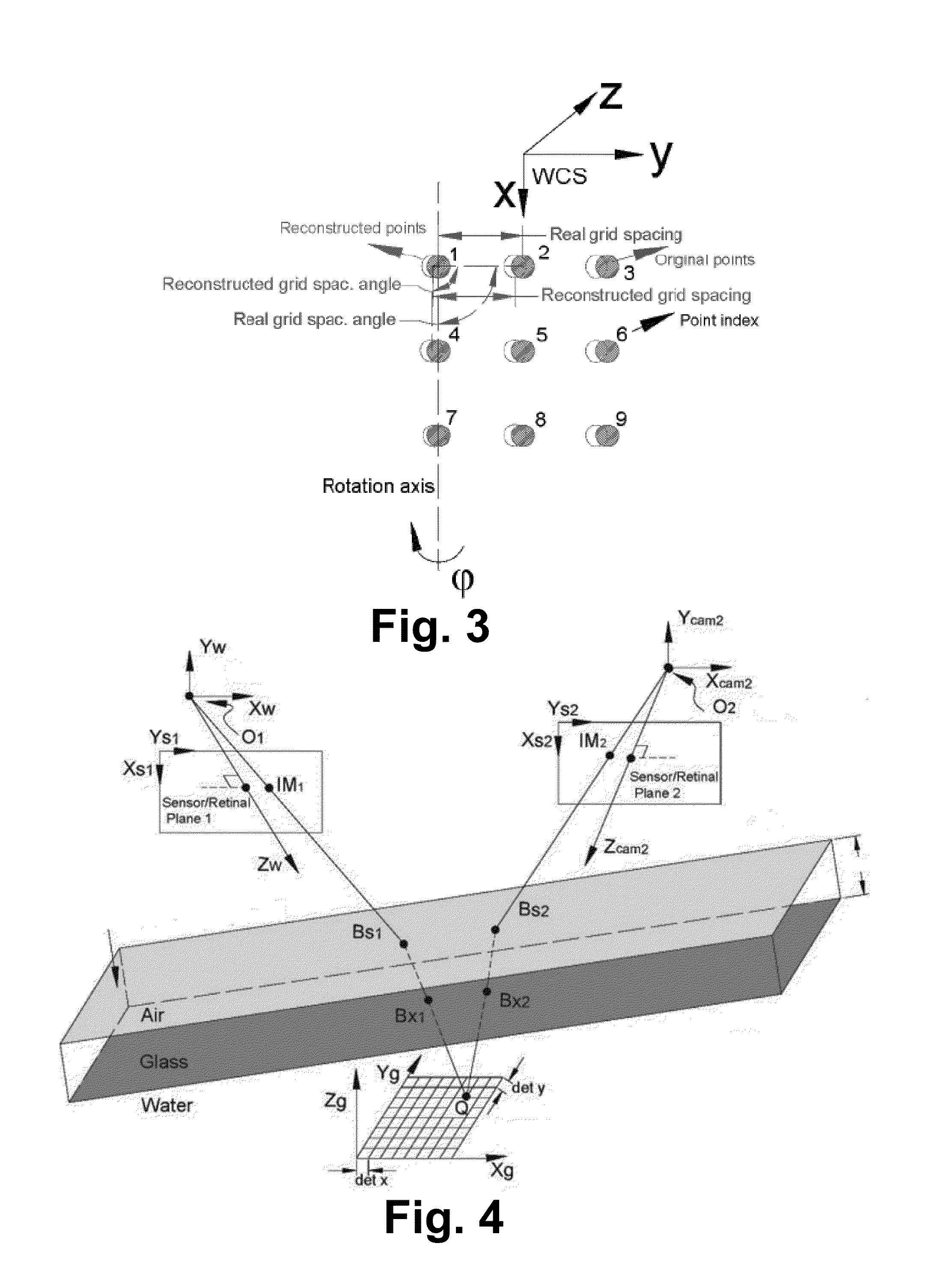
[0079]As a first numeric simulation to illustrate aspects of the present invention, parameters from a Nikon SMZU stereo-microscopy system were used in an exemplary measurement system having a schematic similar to that shown in FIG. 4. Camera 2's local coordinate system (camCS) was obtained by initially equaling camCS to WCS, rotating the camCS around WCS's y-axis as angle y=6.0° (clockwise), then translating camCS to (50.0, 0.0, 0.0) in WCS. The rotation matrix [R] and {T} in Eq. (5) for camera 2 was
[R]=[0.99450.00.10450.01.00.0-0.10450.00.9945]and{T}={-50.00.00.0}.
The projection matrixes for two cameras in Eq. (7b) were
[Mp]_cam1=[17600.0100.04200.00.017600.0420.00.00.01.0],[Mp]_cam2=[18000.0-50.0-3200.00.018000.0250.00.00.01.0].
[0080]The interface parameters a, b and d were 0.1, 0.2 and −150.0. The thickness of the interface (TH) was 6.0. The refraction indexes for media A, media G and media W were 1.0, 1.82 and 1.33, respectively. A calibration grid of 9 by 9 points with 1.2 mm sp...
example 2
[0088]As a second example, a stereo system set-up for numerical simulation was established as shown in FIG. 4. The WCS is defined at camera l's local coordinate system. Camera 2's local coordinate system (camCS2) is obtained by initially equaling camCS2 to the WCS, rotating the camCS2 around the WCS y-axis 30.0° (clockwise), then translating camCS2 to (550.0, 0.0, 0.0) in the WCS. The rotation matrix [R] and {T} in equation (5) for camera 2 are written as
[R]=[0.99450.00.10450.01.00.0-0.10450.00.9945]and{T}={-50.00.00.0}
The projection matrices for two cameras in equation (7b) are
[Mp]_cam1=[12000.05.0730.00.012000.0530.00.00.01.0],[Mp]_cam2=[11850.06.0740.00.011850.0520.00.00.01.0].
where [Mp] is selected based on a typical stereo camera set-up. For simplicity, the lens distortion factor κ is set to zero. The interface parameters a, b and d are 0.1, 0.2, and −800.0, respectively. The thickness of the glass TH is 3.0 mm. The refractive indices for air, glass, and water are 1.00, 1.77 an...
PUM
 Abstract
Description
Claims
Application Information
 - R&D
- Intellectual Property
- Life Sciences
- Materials
- Tech Scout
- Unparalleled Data Quality
- Higher Quality Content
- 60% Fewer Hallucinations
Browse by: Latest US Patents, China's latest patents, Technical Efficacy Thesaurus, Application Domain, Technology Topic, Popular Technical Reports.
© 2025 PatSnap. All rights reserved.Legal|Privacy policy|Modern Slavery Act Transparency Statement|Sitemap|About US| Contact US: help@patsnap.com


