Liquid crystal display device equipped with a photovoltaic conversion function

a liquid crystal display and conversion function technology, applied in semiconductor devices, optics, instruments, etc., can solve the problems of enlarge the size of the entire display system, the solar cell is not able to generate electricity through photovoltaic conversion, and the device is difficult to achieve high photovoltaic efficiency, so as to achieve effective power generation of solar cells and minimize the size of the whole display system

Inactive Publication Date: 2010-04-01
TPO HONG KONG HLDG
View PDF6 Cites 56 Cited by
  • Summary
  • Abstract
  • Description
  • Claims
  • Application Information

AI Technical Summary

Benefits of technology

[0012]Another object of the present invention is to provide a display device in which power generation of the solar cell can be carried out effectively despite the fact that the display section is covered up by some other articles.
[0013]Still another object of the present invention is to provide a display device which is enabled to generate power by performing photovoltaic conversion for incident light entering the display panel, and which is advantageous in minimizing the size of the whole display system.

Problems solved by technology

Before the incident light reaches the solar cell, there may be attenuation of the light to a certain extent, and thus, it is hard to attain high photovoltaic efficiency with the device.
When the user is not aware of the cell phone's display mode and the display section is covered up by some other objects, the solar cell is not able to generate electricity through photovoltaic conversion.
Besides, disposing the solar cell unit separate from the liquid crystal panel (“liquid crystal cell” in cited reference 2) tends to enlarge the size of the entire display system.

Method used


Image

  • Liquid crystal display device equipped with a photovoltaic conversion function
  • Liquid crystal display device equipped with a photovoltaic conversion function
  • Liquid crystal display device equipped with a photovoltaic conversion function

Examples


Embodiment Construction

[0027]The present invention will be apparent from the following detailed description, which proceeds with reference to the accompanying drawings, wherein the same references relate to the same elements.

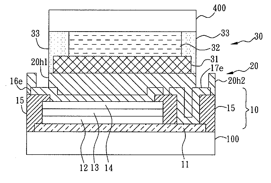
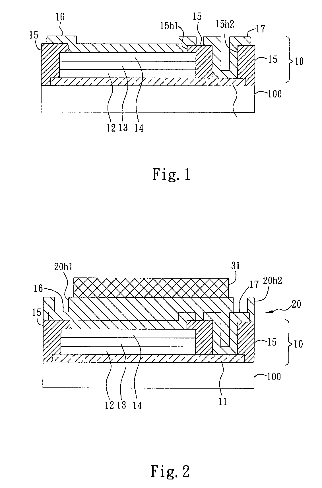
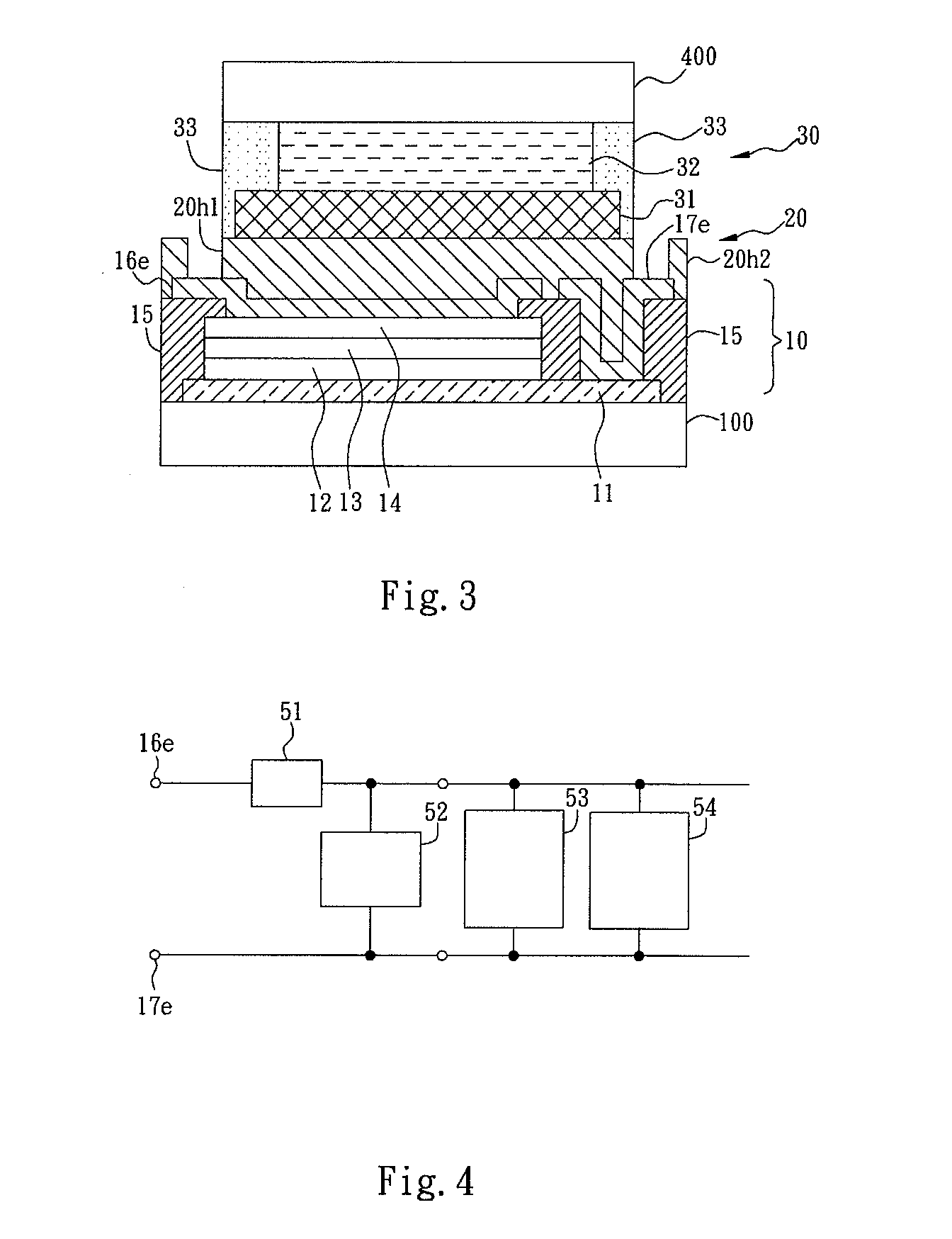
[0028]FIGS. 1 to 3 are schematic sections showing major steps for fabricating a liquid crystal display device according to an embodiment of the present invention.

[0029]FIG. 1 shows the step of forming a solar cell layer on a rear substrate. First, a rear substrate 100 made of glass or other light transmissive thin film is provided. With the substrate 100 as a base layer, a thin film, such as an indium tin oxide (ITO) thin film, is formed on it to constitute a transparent conductive layer 11. The transparent conductive layer 11 occupies most of the major surface area on the rear substrate 100, while as shown in FIG. 1, both ends of the conductive layer 11 do not exceed the ending boundaries of the rear substrate 100. In this embodiment, a solar cell of PIN structure is employed, and th...


PUM

PropertyMeasurementUnit
specific areaaaaaaaaaaa
transparentaaaaaaaaaa
n-type semiconductoraaaaaaaaaa

Abstract

A solar cell construction in a display device is provided. The photovoltaic conversion can be performed with high efficiency by the solar cell construction. The display device includes a front substrate and an opposing rear substrate, which are light-transmissive. The display device further includes an optical control layer, a solar cell layer and an insulating flattened layer. The optical control layer is disposed between the substrates, wherein images formed by the optical control layer are displayed on the outer side of the front substrate. The solar cell layer is disposed in a specific area of the major surface on the rear substrate, between the rear substrate serving as a base for supporting it and the optical control layer, and receives incident light coming from the external surroundings through the rear substrate. The insulating flattened layer is formed on the solar cell layer, wherein the optical control layer is formed on and supported by the insulating flattened layer.

Description

BACKGROUND OF THE INVENTION[0001]1. Field of Invention[0002]The present invention relates to a liquid crystal display device equipped with a photovoltaic conversion function, and more particularly to a liquid crystal display device with a solar cell construction.[0003]2. Related Art[0004]In certain previous researches, there were proposed a technique of assembling solar cells in a liquid crystal display device where the solar cells generated the electricity required for the driving device and / or the battery charging device.[0005]A liquid crystal display device of the above type has been disclosed in cited reference 1, where the device is a reflection type liquid crystal electro-optic device. In the display device according to this invention, a dispersion mold liquid crystal layer is sandwiched between two transparent substrates, and a solar cell is formed on the bottom substrate. By using one part of the solar cell as the active component, the technique for driving the dispersion mo...

Claims


Application Information

Patent Timeline
Patent Type & Authority Applications(United States)
IPC IPC(8): G02F1/133
CPCG02F1/13306G02F2001/13324Y02E10/548H01L31/075Y02E10/52H01L31/04G02F1/13324
Inventor TANAKA, HIDEO
Owner TPO HONG KONG HLDG
Why Eureka
Try Eureka