Process for adjusting the size and shape of nanostructures

a nanostructure and nano-structure technology, applied in the field of nano-scale devices manufacturing, can solve the problems of reducing the lateral dimension etc., and achieve the effects of reducing the lateral dimension of micro-scale devices on substrates, reducing the lateral dimension of line spacing or the size of holes, and increasing the size of mesas

Active Publication Date: 2010-04-01
CHOU +3
View PDF5 Cites 10 Cited by
  • Summary
  • Abstract
  • Description
  • Claims
  • Application Information

AI Technical Summary

Benefits of technology

[0010]In accordance with the invention, a lateral dimension of a microscale device on a substrate is reduced or adjusted by the steps of providing the device with a soft or softened exposed surface; placing a guiding plate adjacent the soft or softened exposed surface; and pressing the guiding plate onto the exposed surface. Under pressure, the soft material flo...

Problems solved by technology

Such pressure induced flow can reduce the lateral dimension o...

Method used


Image

  • Process for adjusting the size and shape of nanostructures
  • Process for adjusting the size and shape of nanostructures
  • Process for adjusting the size and shape of nanostructures

Examples


examples

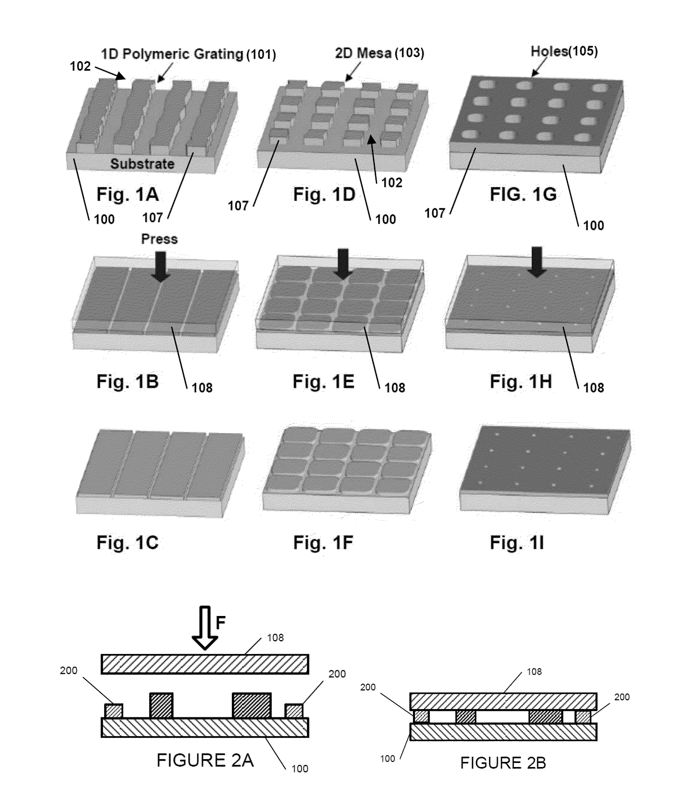
[0046]We have demonstrated P-SPEL in thermoplastic polymer nanostructures on Si or SiO2 substrates. The initial nanostructures were fabricated using thermal nanoimprinting for patterning and Reactive Ion Etching (RIE) for removing the residue resist layer (at the bottom of recessed nanostructures). We used a Si wafer with a featureless smooth surface as the guiding plate and used an Air Cushion Press TM (Nanonex NX-2000 imprinter) or a parallel plate press to press the samples. Preferably the pressing is highly uniform as could be obtained by using direct fluid pressure to press together the guiding plate and the substrate. See U.S. Pat. No. 6,482,742. The final gap between the guiding plate and the substrate was controlled by processing time (since a material flow takes time) in most our experiments. A micro-stopper was used in some cases.

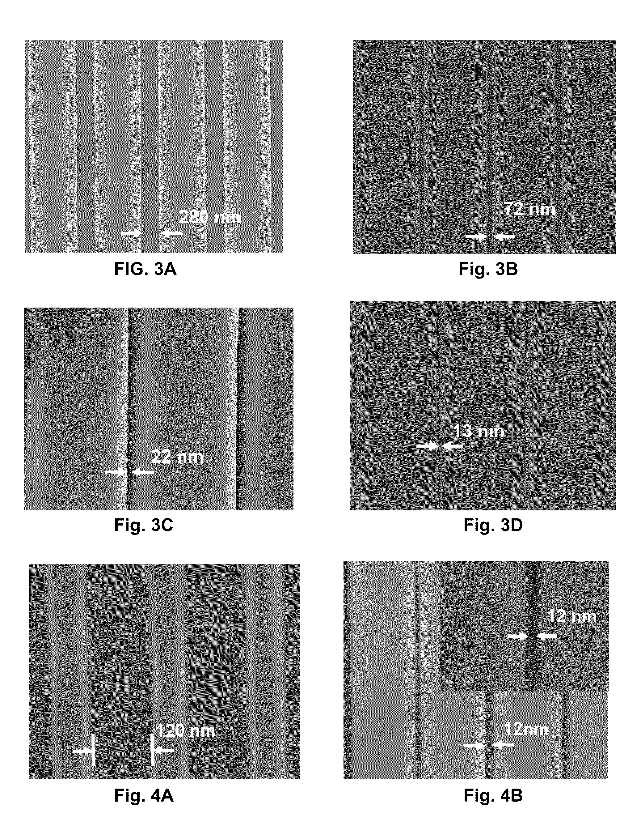
[0047]FIG. 3 shows the results of P-SPEL on the grating lines made of a linear acrylate polymer (a thermoplastic with a glass transition temperat...


PUM

PropertyMeasurementUnit
Lengthaaaaaaaaaa
Thicknessaaaaaaaaaa
Thicknessaaaaaaaaaa

Abstract

In accordance with the invention, a lateral dimension of a microscale device on a substrate is reduced or adjusted by the steps of providing the device with a soft or softened exposed surface; placing a guiding plate adjacent the soft or softened exposed surface; and pressing the guiding plate onto the exposed surface. Under pressure, the soft material flows laterally between the guiding plate and the substrate. Such pressure induced flow can reduce the lateral dimension of line spacing or the size of holes and increase the size of mesas. The same process also can repair defects such as line edge roughness and sloped sidewalls. This process will be referred to herein as pressed self-perfection by liquefaction or P-SPEL.

Description

CROSS-REFERENCE TO RELATED APPLICATIONS[0001]The present application is a continuation-in-part of U.S. application Ser. No. 12 / 419,881 filed by Stephen Y. Chou, et al. on Apr. 7, 2009 which, in turn, is a continuation-in-part of U.S. application Ser. No. 11 / 915,090 filed Jun. 11, 2008 which is the §371 National Stage of PCT Application No. PCT / US2006 / 020686, filed May 29, 2006, which in turn claims priority from U.S. Provisional Patent Application Ser. No. 60 / 685,277 filed on May 27, 2005 and U.S. Provisional Patent Application Ser. No. 60 / 685,940 filed on May 31, 2005, all of the aforementioned applications are herein incorporated by reference.[0002]The '881 application is further related to and claims priority to U.S. Provisional Application No. 61 / 043,025, filed on Apr. 7, 2008, which is herein incorporated by reference.[0003]The present application is further related to, and claims priority to, U.S. Provisional Application Ser. No. 61 / 050,070 filed on May 2, 2008, which is herei...

Claims


Application Information

Patent Timeline
IPC IPC(8): H01L21/306B29C59/02B44C1/22G03F1/00H01L21/312
CPCH01L21/0273Y10S977/888Y10S977/90
Inventor CHOU, STEPHEN Y.WANG, YINGLIANG, XIAOGANLIANG, YIXING
Owner CHOU
Why Eureka
Try Eureka