Posterior fixation device for percutaneous stabilization of thoracic and lumbar burst fractures

Inactive Publication Date: 2010-04-01
UNIVERSITY OF TOLEDO
View PDF10 Cites 45 Cited by
  • Summary
  • Abstract
  • Description
  • Claims
  • Application Information

AI Technical Summary

Benefits of technology

[0011]In yet another variation, the central hole through the rod may permit insertion of non-locking screws utilizing either sequence described above. Finally, if the pedicle is fractured, placing a pedicle screw at this level may not be advisable. In this setting, a “filler” locking screw may be inserted that fills the hole within the rod but does not anchor the vertebra below. This arrangement will improve the strength of the rod. The rod of such description may be designed to encompass more than one vertebra above or below the fracture level to suit the requirements of any given patient.
[0012]The vertebral fasteners for fixation to the intact vertebra above and below the fracture may

Problems solved by technology

It may be incomplete such that it allows real

Method used


Image

  • Posterior fixation device for percutaneous stabilization of thoracic and lumbar burst fractures
  • Posterior fixation device for percutaneous stabilization of thoracic and lumbar burst fractures
  • Posterior fixation device for percutaneous stabilization of thoracic and lumbar burst fractures

Examples


first embodiment

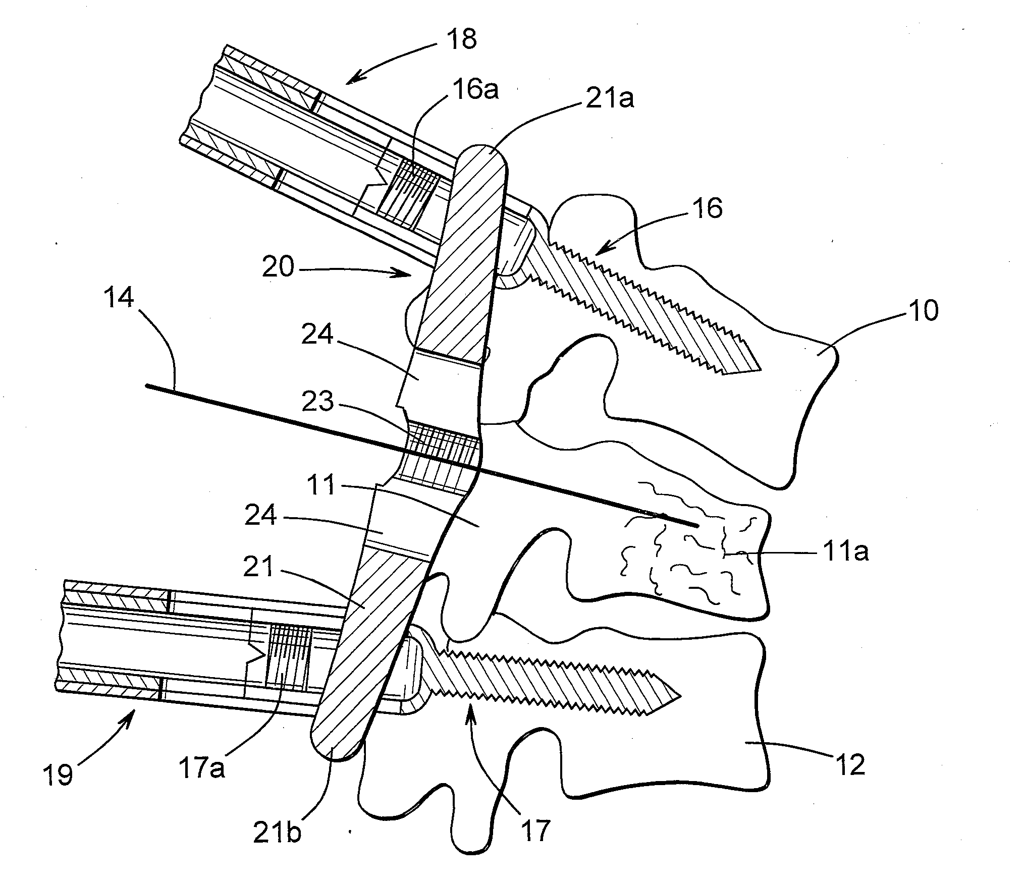
[0036]FIGS. 4 through 7 illustrated a fixation rod, indicated generally at 20, in accordance with this invention. As shown therein, the fixation rod 20 includes a body 21 that is generally elongated and cylindrical in shape, having end portions 21a and 21b that are generally semi-spherical in shape. However, the body 21 of the fixation rod 20 may be formed having any desired shape. The illustrated fixation rod 20 is slightly curved from one end to the other, although such is not required. In the illustrated embodiment, the fixation rod 20 has a length that is suited for use in aligning the three vertebrae 10, 11, and 12 in the manner described below. However, the body 21 of the fixation rod 20 may have any desired length.

[0037]The body 21 of the fixation rod 20 may be formed from any desired material, such as titanium, stainless steel, and cobalt-chrome, and it may have any desired coating or finish. It may also be formed from other materials, such as PEEK, but preferably is formed ...

second embodiment

[0048]FIGS. 15 through 18 illustrated a fixation rod, indicated generally at 50, in accordance with this invention. As shown therein, the fixation rod 50 includes a body 51 that is generally elongated and cylindrical in shape, having end portions 51a and 51b that are generally semi-spherical in shape. However, the body 51 of the fixation rod 50 may be formed having any desired shape. The illustrated fixation rod 50 is slightly curved from one end to the other, although such is not required. In this second illustrated embodiment, the fixation rod 50 has a length that is suited for use in aligning the three vertebrae 10, 11, and 12 in the manner described below. However, the body 51 of the fixation rod 50 may have any desired length. The body 51 of the fixation rod 50 may be formed from any desired material, but preferably is formed from a material that is relatively rigid and is suited for internal use within the human body.

[0049]The body 51 of the fixation rod 50 has an aperture, in...


PUM


Abstract

A spinal fixation device includes a fixation rod including a body having an aperture formed therethrough. First and second vertebral fasteners are secured to the body and are adapted to be secured to respective vertebrae. A third vertebral fastener extends through the aperture in the body of the fixation rod and adapted to be secured to a vertebra.

Description

STATEMENTS REGARDING FEDERALLY SPONSORED RESEARCH OR DEVELOPMENT AND CROSS REFERENCE TO RELATED APPLICATIONS[0001]This invention was not made with any government support. This application claims the benefit of U.S. Provisional Application No. 61 / 101,532 filed Sep. 30, 2008, the disclosure of which is incorporated herein by reference.BACKGROUND OF THE INVENTION[0002]This invention relates to the field of orthopedic surgery and more particularly to the area of spinal surgery. Specifically, this invention relates to an improved fixation rod for use in stabilizing thoracic and lumbar spinal burst fractures and to a method for using same.[0003]Fractures of the vertebrae of the human spine can range from mildly painful conditions to serious life-threatening situations. One basis for classifying such spinal fractures is whether they are stable or unstable. Generally speaking, a stable fracture is a fracture of a vertebra that does not cause any spinal deformity or neurological problems. St...

Claims


Application Information

Patent Timeline
IPC IPC(8): A61B17/70
CPCA61B17/7007A61B17/7032A61B17/8855A61B17/864A61B17/7085
Inventor BIYANI, ASHOK
Owner UNIVERSITY OF TOLEDO
Why Eureka
Try Eureka