Method for the Detection of Errors in Pump Units

a technology for fault detection and pump units, applied in the direction of fluid pressure measurement by mechanical elements, solids vibration measurement, blast furnace, etc., can solve the problems of impeller damage, contamination, damage, etc., and achieve the effect of reliable and simple manner

Active Publication Date: 2010-04-01
GRUNDFOS MANAGEMENT AS
View PDF5 Cites 23 Cited by
  • Summary
  • Abstract
  • Description
  • Claims
  • Application Information

AI Technical Summary

Benefits of technology

[0004]With regard to this problem, it is an object of the invention to provide a method as well as corresponding devices, with which different faults in a pump assembly having an electric motor or faults in an electric motor may be detected in a reliable and simple manner.

Problems solved by technology

Different faults, in particular bearing damage, may occur in pump assemblies which are driven by electric motors, or also in electric motors themselves, or also damage to impellers or contamination may occur in the pump assemblies.

Method used


Image

  • Method for the Detection of Errors in Pump Units
  • Method for the Detection of Errors in Pump Units
  • Method for the Detection of Errors in Pump Units

Examples


Embodiment Construction

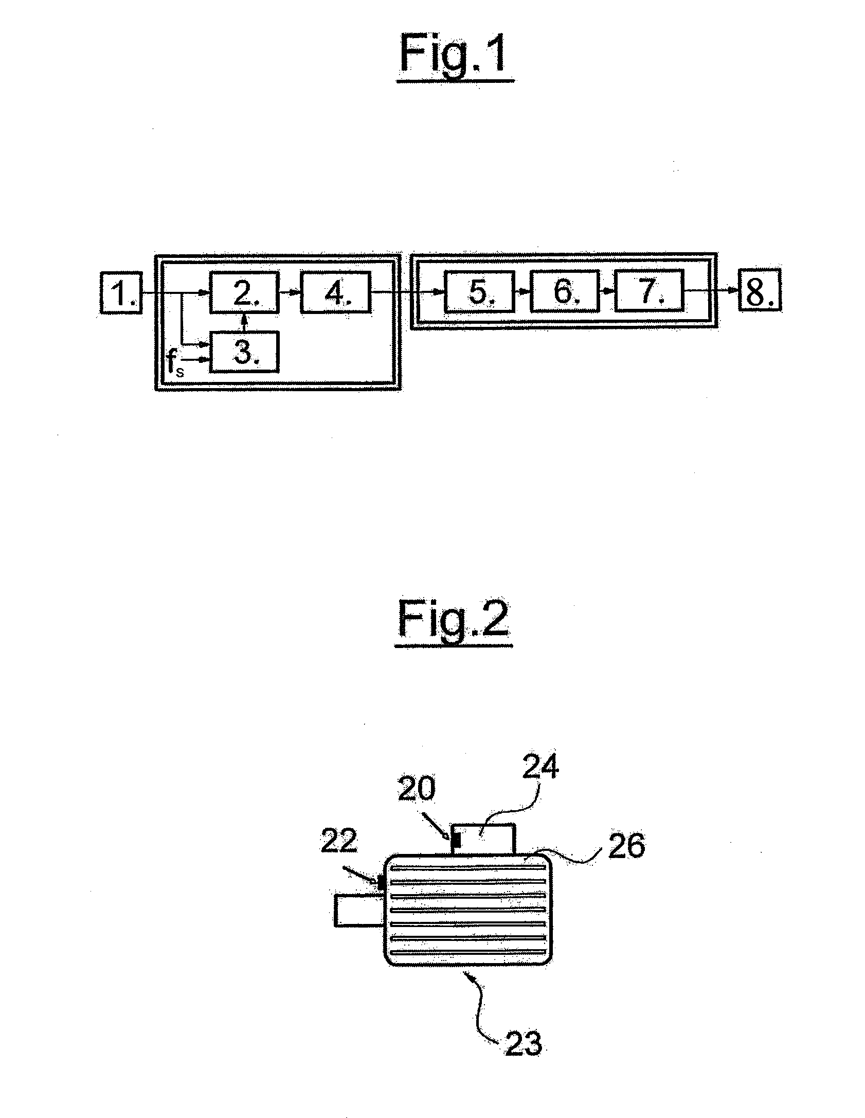
[0040]Hereinafter, the basic procedure of the method according to one preferred embodiment of the invention is described with reference to FIG. 1.

[0041]In step 1 in FIG. 1, a vibration measurement or a vibration signal detection takes place by a suitable sensor, for example an acceleration sensor, an optical sensor, a microphone or hydrophone. The output signal of this sensor or of the vibration measurement is provided for the steps 2 and 3. In step 2, a signal preparation or signal processing is effected, in which the influence of the current rotational speed of the motor shaft or of the pump impeller is minimized or eliminated, depending on the apparatus into which the fault recognition system according to the invention is integrated. This processing of the vibration signal is effected by a resampling with a sampling frequency, which is related to a constant predefined rotational speed. For this, the current sampling frequency is multiplied by the current rotational speed and divi...


PUM

PropertyMeasurementUnit
rotational speedaaaaaaaaaa
rotation speedaaaaaaaaaa
speedaaaaaaaaaa

Abstract

A method is provided for detecting faults in a pump assembly having an electric motor, or faults in an electric motor, having at least one rotating shaft. A vibration signal is detected, the detected vibration signal is processed in a manner such that the influence of the current rotational speed of the shaft is eliminated, periodic signals are filtered out of the processed vibration signal, and the vibrational operating condition, in particular possible faults, is recognized by way of the periodic signals. Further, a pump assembly having an electric motor or an electric motor is provided in which this method is applied.

Description

CROSS-REFERENCE TO RELATED APPLICATIONS[0001]This application is a Section 371 of International Application No. PCT / EP2008 / 001449, filed Feb. 23, 2008, which was published in the German language on Oct. 2, 2008, under International Publication No. WO 2008 / 116538 A1 and the disclosure of which is incorporated herein by reference.BACKGROUND OF THE INVENTION[0002]The invention relates to a method for detecting faults in a pump assembly having an electric motor, or faults in an electric motor.[0003]Different faults, in particular bearing damage, may occur in pump assemblies which are driven by electric motors, or also in electric motors themselves, or also damage to impellers or contamination may occur in the pump assemblies. It is desirable to be able to detect these faults as early as possible, in order to be able to exchange such an assembly or to overhaul it in good time, before a complete failure of the assembly occurs.BRIEF SUMMARY OF THE INVENTION[0004]With regard to this problem...

Claims


Application Information

Patent Timeline
Patent Type & Authority Applications(United States)
IPC IPC(8): G01L7/00G01N29/04
CPCF04D15/0066F04D29/669F04D15/0088F05D2270/709
Inventor BORSTING, HAKONMUNK, FLEMMING
Owner GRUNDFOS MANAGEMENT AS
Why Eureka
Try Eureka