Postal service revenue protection with real-time processing

a technology of revenue protection and postage protection, applied in the field of postal service revenue protection with real-time processing, can solve the problems of many sheets and weight, bank failure to properly post the heavier pieces, and the loss of millions of dollars in the us postal service each year

Active Publication Date: 2010-04-01
VELOX ROBOTICS LLC
View PDF35 Cites 22 Cited by
  • Summary
  • Abstract
  • Description
  • Claims
  • Application Information

AI Technical Summary

Benefits of technology

[0006]The following is a summary of the invention in order to provide a basic understanding of some aspects of the invention. This summary is not intended to identify key / critical elements of the invention or to delineate the scope of the invention. Its sole purpose is to present some concepts of the invention in a simplified form as a prelude to the more detailed description that is presented later.

Problems solved by technology

While this may be a problem with individual private persons, for political reasons the US Postal Service (and others) does not generally target individual mail pieces that may be slightly overweight.
Most statements contain a few sheets and easily fit under the one ounce cut-off, but some of them contain many sheets and are overweight.
Very often the banks do not put proper postage on the heavier pieces.
Audits, sometimes run by manually weighing suspect mail pieces, indicate that the US Postal Service loses many millions of dollars each year because of this practice.
Because current methods of weighing mail pieces are either too slow for existing sorting machines or require individual or a set of mail pieces to be weighed manually, postal services have not devised methods for ensuring proper postage on each mail piece.
As a result, a set of mail pieces whose average weight is under the limit may still contain many mail pieces that are individually too heavy and require greater postage.

Method used


Image

  • Postal service revenue protection with real-time processing
  • Postal service revenue protection with real-time processing
  • Postal service revenue protection with real-time processing

Examples


second embodiment

[0019]FIG. 9A is a top plan view of a transport assembly of an in-line weighing apparatus in a non-weighing state.

[0020]FIG. 9B is a top plan view of the transport assembly of FIG. 9A in a weighing state.

[0021]FIG. 10A is an exploded, perspective view of the transport assembly of FIG. 9A.

[0022]FIG. 10B is an assembled, perspective view of the transport assembly of FIG. 9A.

third embodiment

[0023]FIG. 11A is a top plan view of a transport assembly of an in-line weighing apparatus in a non-weighing state.

[0024]FIG. 11B is a top plan view the a transport assembly of FIG. 11A in a weighing state.

[0025]FIG. 11C is an exploded, perspective view of the transport assembly of FIG. 11A.

[0026]FIG. 11D is an assembled, perspective view of the transport assembly of FIG. 11A.

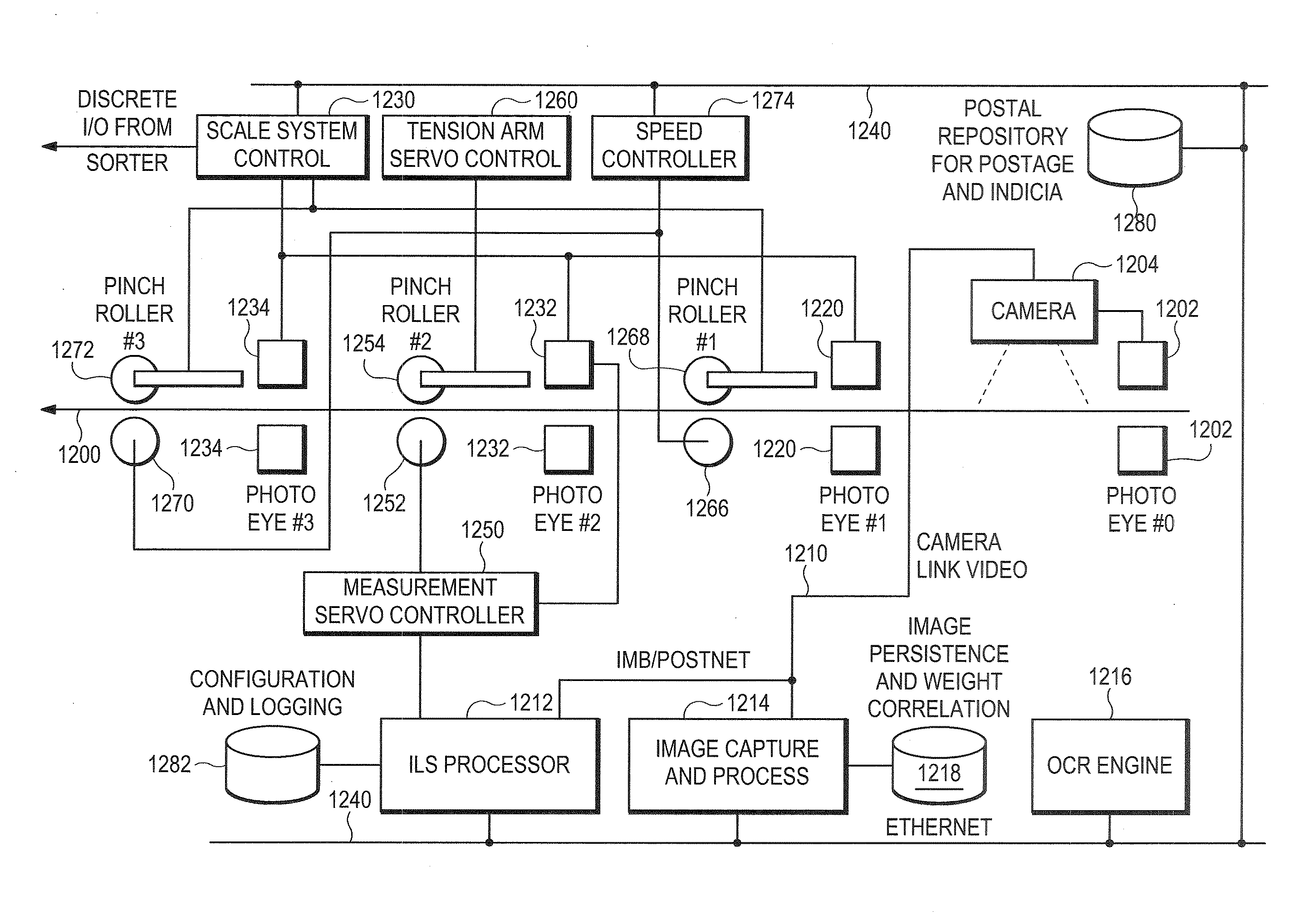
[0027]FIG. 12 is a simplified electronic system diagram of a dual-servo controlled in-line weighing apparatus in the context of a mail sorting system.

[0028]FIG. 13 is a side view of an embodiment of a dual-servo in-line weighing apparatus.

[0029]FIG. 14 is a top plan view the weighing apparatus of FIG. 13.

[0030]FIG. 15 is an enlarged top view taken along line 15-15 of FIG. 13 showing drive linkage detail of the weighing assembly of the weighing apparatus of FIG. 13.

[0031]FIG. 16 is a perspective view of the weighing assembly with the deck shown in phantom.

[0032]FIG. 17 is a perspective view of a tension arm stan...


PUM


Abstract

Methods and apparatus for weighing an article, such as a mail piece, while the article is moving at high speed, and for checking that the correct amount of postage has been paid for delivery of the article. An article (900) is received from an intake transport (1200), and gripped in a weighing station (1310), in between a capstan roller and a pinch roller (1316), which are synchronized to minimize slipping. A first precision closed-loop servo system (1252, 1250) alters the speed of the article, and in the process acquires torque data for storage and analysis (1212, 1282) to determine weight. Correct postage is determined in a processor (1212), and the postage actually paid is checked either by image analysis (1204, 1214, 1280) or by accessing a stored mailer manifest (1280).

Description

RELATED APPLICATIONS[0001]This application is a continuation-in-part (CIP) of U.S. application Ser. No. 12 / 562,798 filed Sep. 18, 2009, incorporated herein in its entirety by this reference (attorney docket 29094-0041). This application also claims priority to U.S. Provisional Application No. 61 / 101,995 filed Oct. 1, 2008 and incorporated herein in its entirety by this reference (attorney docket 29094-0060).TECHNICAL FIELD[0002]This invention pertains to methods and apparatus for accurately weighing mail pieces or other articles in motion (“on the fly”), and in the case of mail pieces, ensuring that proper postage is paid to the postal service that delivers the mail.COPYRIGHT NOTICE[0003]© 2007-2009 RAF Technology, Inc. A portion of the disclosure of this patent document contains material which is subject to copyright protection. The copyright owner has no objection to the facsimile reproduction by anyone of the patent document or the patent disclosure, as it appears in the Patent a...

Claims


Application Information

Patent Timeline
Patent Type & Authority Applications(United States)
IPC IPC(8): G06Q50/00G06Q10/00B65G1/00B65G49/00G01G19/03
CPCG01G19/005G01G19/035G06Q30/0283G06Q10/083G01G19/4148
Inventor TURNER, BRYAN
Owner VELOX ROBOTICS LLC
Why Eureka
Try Eureka