Information processing apparatus and its control method and data processing system

a technology of information processing apparatus and control method, applied in the field of information processing apparatus, can solve problems such as difficult to understand diagnostic information (schema) showing, complicated shapes, and inability to easily draw using a mouse or a tabl

Inactive Publication Date: 2010-04-01
CANON KK
View PDF2 Cites 21 Cited by
  • Summary
  • Abstract
  • Description
  • Claims
  • Application Information

AI Technical Summary

Benefits of technology

[0016]According to the present invention, it is possible to provide a technique which enables efficient understanding of captured images of troubled parts and supporting diagnostic information of the images.

Problems solved by technology

However, when creating an illustration (called “basic schema”) indicating body structures in a schema, it is necessary to draw complicated shapes, which cannot be easily drawn using a mouse or a tablet.
However, with the above-mentioned method, although it is possible to understand temporal changes in disease loci from the captured images of the disease loci, it is not possible to understand diagnostic information (schema) showing how the physician characterized the disease loci and arrived at the decision.

Method used


Image

  • Information processing apparatus and its control method and data processing system
  • Information processing apparatus and its control method and data processing system
  • Information processing apparatus and its control method and data processing system

Examples


first embodiment

[0030]An example of a diagnosis supporting apparatus in a data processing system will be explained below as a first embodiment of the present invention.

[0031]

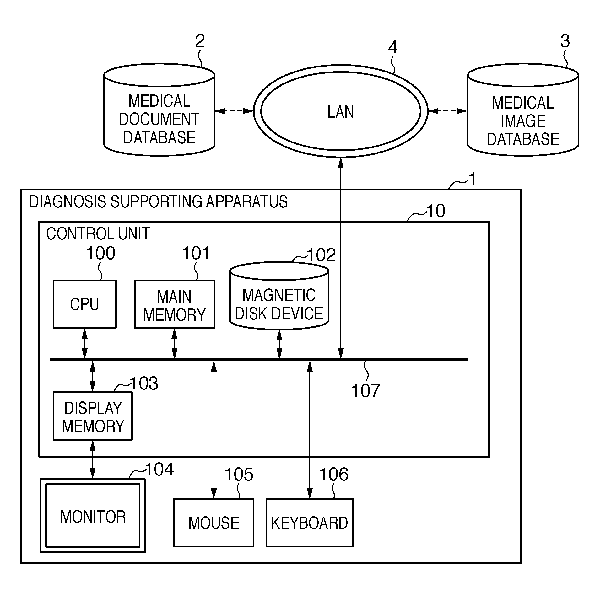
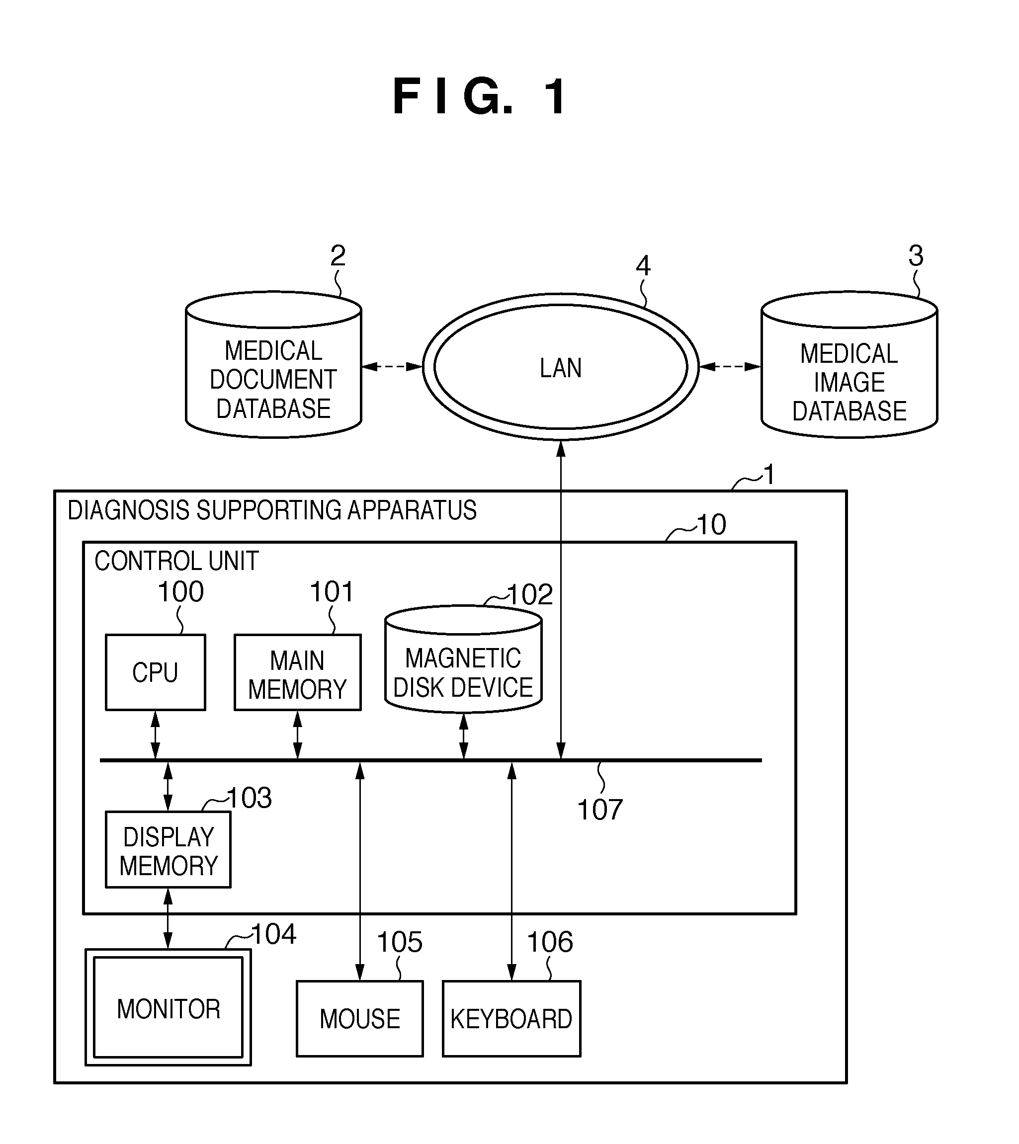
[0032]FIG. 1 indicates configuration of a diagnosis supporting apparatus 1 according to the first embodiment of the present invention.

[0033]The diagnosis supporting apparatus 1 has a control unit 10, a monitor (display unit) 104, a mouse 105, and a keyboard 106. The control unit 10 has a central processing unit (CPU) 100, a main memory 101, a magnetic disc 102, and a display memory 103. Various types of control, such as communication between a medical document database 2 and a medical image database 3, overall control of the diagnosis supporting apparatus 1, etc, are performed by execution of programs stored in the main memory 101 by the CPU.

[0034]Further, the diagnosis supporting apparatus 1 is connected to the medical image database 3 which can capture image of examination subjects. The medical image database 3 stores image d...

second embodiment

[0083]In the second embodiment, a configuration in which a schema and the feature amount of the disease locus image corresponding to the schema are displayed in conjunction will be explained. The structure of the diagnosis supporting apparatus according to the second embodiment will be omitted since it is identical to that according to the first embodiment. However, as explained below, the control program executed by the CPU is different from that of the first embodiment. In other words, the program stored in the magnetic disc 102 is different.

[0084]FIG. 7 is a flowchart of operation of the diagnosis supporting apparatus according to the second embodiment. Detailed explanation of steps in which processing that are identical to those shown in the flow chart in FIG. 2 of the first embodiment will be omitted.

[0085]Processing in steps S701 to 5711 are identical to those in steps S201 to 5211 of the first embodiment.

[0086]At step S712, the CPU 100 calculates, for the 1st to the nth medic...

example 1

Variant Example 1

[0094]Generation the disease locus time-series quantitative data at step S712 and the coupled presentation of the time-series data at step S713 can also be arranged as follows.

[0095]FIG. 10 shows a disease locus temporal change table which shows the quantitative data of the disease locus organized into a table. Like the disease locus temporal change graph of step S712, effective radii of nodal shades are shown as quantitative data of the disease locus.

[0096]Then in step S713, processing to display the disease locus time-series schema and the disease locus temporal change chart in conjunction is performed. For example, when a specific examination data is selected in the disease locus temporal change chart, the data in the corresponding disease locus time-series schema can be highlighted for display.


PUM


Abstract

In order to provide a technology which allows efficient understanding of images of a disease locus and diagnosis supporting information for the images, an information processing apparatus comprises: an input unit which inputs object identification information for identifying an object; an acquiring unit which acquires one or more schemas related to the object and medical image data related to the schema, an identification unit which identifies a disease locus region in medical image data respectively related to each of the one or more schemas, a time-series schema generating unit which generates a time-series schema of the disease locus, a time-series image data generating unit which generates time-series image data of the disease locus, and a display output unit which synchronizes and outputs the time-series schema of the disease locus and the time-series image data of the disease locus.

Description

BACKGROUND OF THE INVENTION[0001]1. Field of the Invention[0002]The present invention relates to an information processing apparatus which supports creating medical reports (carte), image diagnosis reports, etc. In particular, the present invention relates to a technique of displaying schema drawn by doctors on medical documents.[0003]2. Description of the Related Art[0004]In the field of medical care, devices for generating medical pictures for examination of the interior of patients' bodies include Computed Radiography (CR) devices, Computed Tomography (CT) devices, Magnetic Resonance Imaging (MRI) devices, and Ultrasound System devices. Physicians display medical images taken by these devices on a monitor, from which conditions and temporal changes of troubled areas are observed, and results of an image diagnosis are recorded in an image diagnostic report as findings information. Doctors, when making diagnostic confirmations for the troubles, record conditions of patients and dis...

Claims


Application Information

Patent Timeline
Patent Type & Authority Applications(United States)
IPC IPC(8): G06F17/30A61B5/00G06T1/00G06V10/25G16H10/60
CPCG06F19/321G06T7/0012G06K2209/05G06K9/3233G16H50/20G16H70/60G16H30/20G06V10/25G06V2201/03
Inventor MIYASA, KAZUHIROIMAMURA, HIROSHIIMAIZUMI, MASAAKISAKAGAWA, YUKIO
Owner CANON KK
Why Eureka
Try Eureka