Test Plug and Method for Monitoring Downstream Conditions

a test plug and downstream condition technology, applied in the field of test plugs, can solve the problems of clogging of vent passageways, reducing measurement accuracy, and requiring precision machining processes

Inactive Publication Date: 2010-04-08
EST GROUP
View PDF15 Cites 17 Cited by
  • Summary
  • Abstract
  • Description
  • Claims
  • Application Information

AI Technical Summary

Benefits of technology

[0008]The present invention advantageously provides a method for measuring pressure and like conditions in a downstream portion of a pipe beyond the seals of a test plug. The method utilizes a transducer to obtain measurements and electronically transmit the information to a control unit which controls a display of the measurements and / or provides a warning indication when measured conditions reach a pre-set level. The method also controls the gradual increase and decrease of start-up and turn-off of power to the transducer within a pipe environment.

Problems solved by technology

While the above-described test plugs may function satisfactorily under certain conditions, a problem with them is that the vent passageways require precision machining processes and are complex, time-consuming and costly to manufacture and maintain.
The vent passageways are also subject to the problem of clogging by material in the pipe.
Such clogging decreases measurement accuracy and increases maintenance.

Method used


Image

  • Test Plug and Method for Monitoring Downstream Conditions
  • Test Plug and Method for Monitoring Downstream Conditions
  • Test Plug and Method for Monitoring Downstream Conditions

Examples


first embodiment

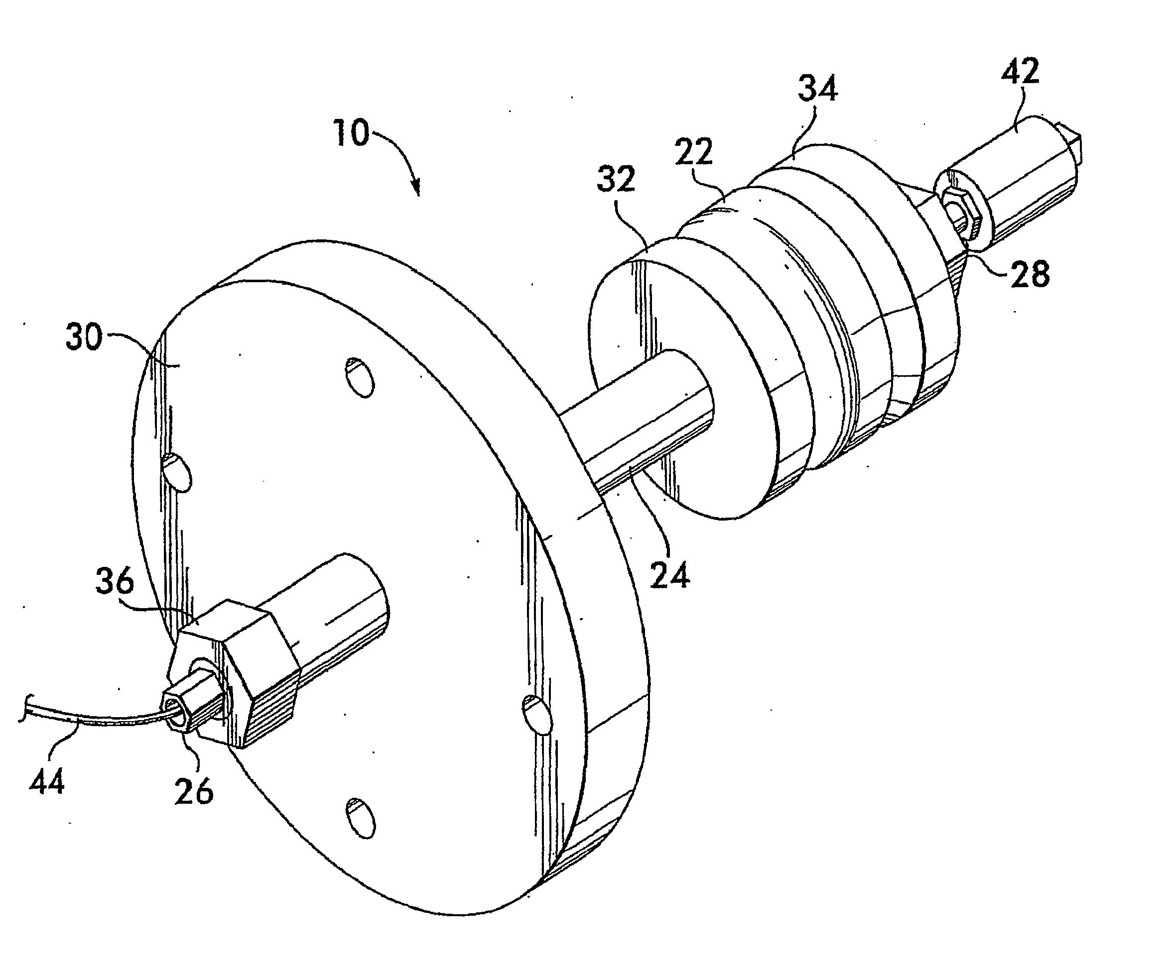
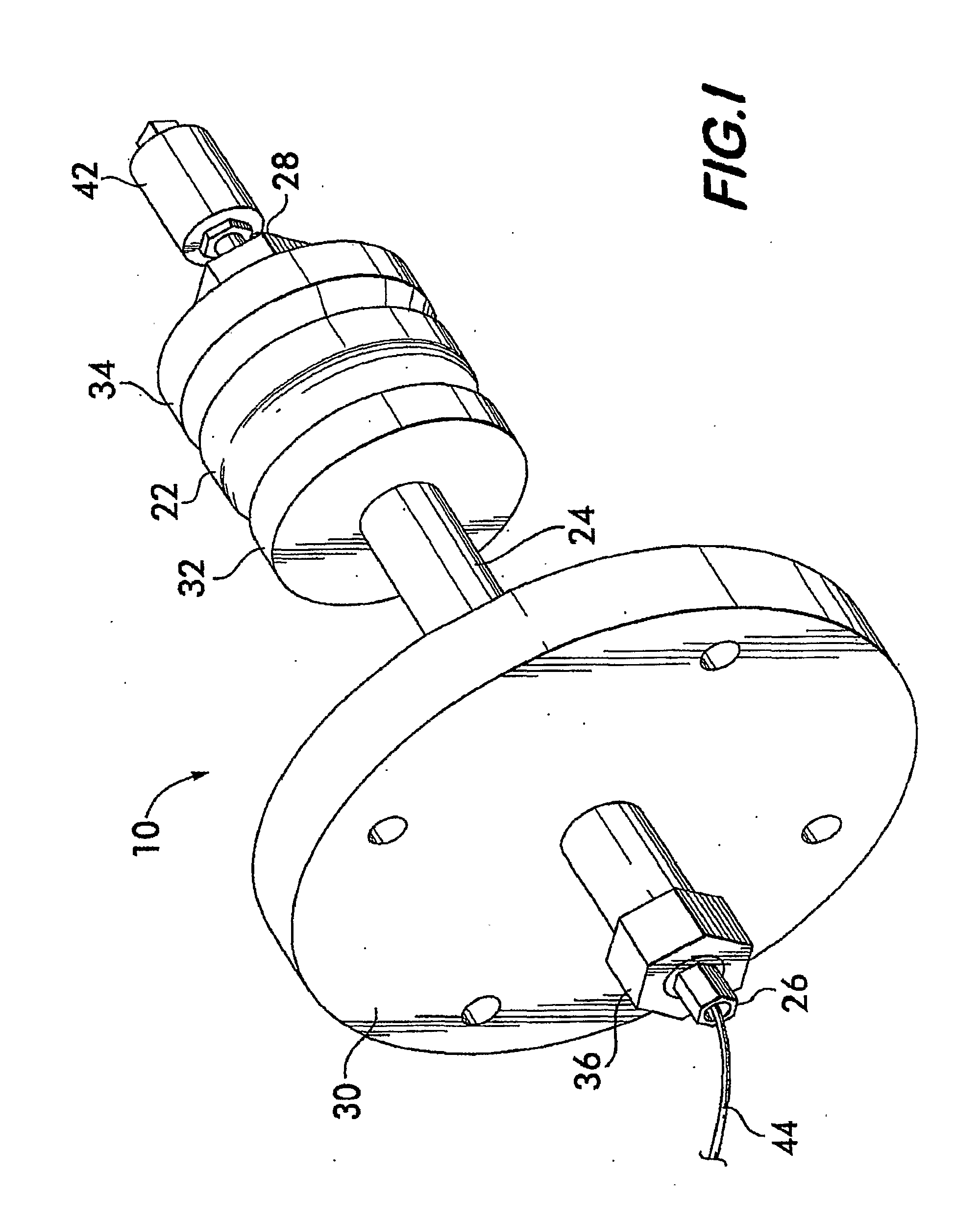
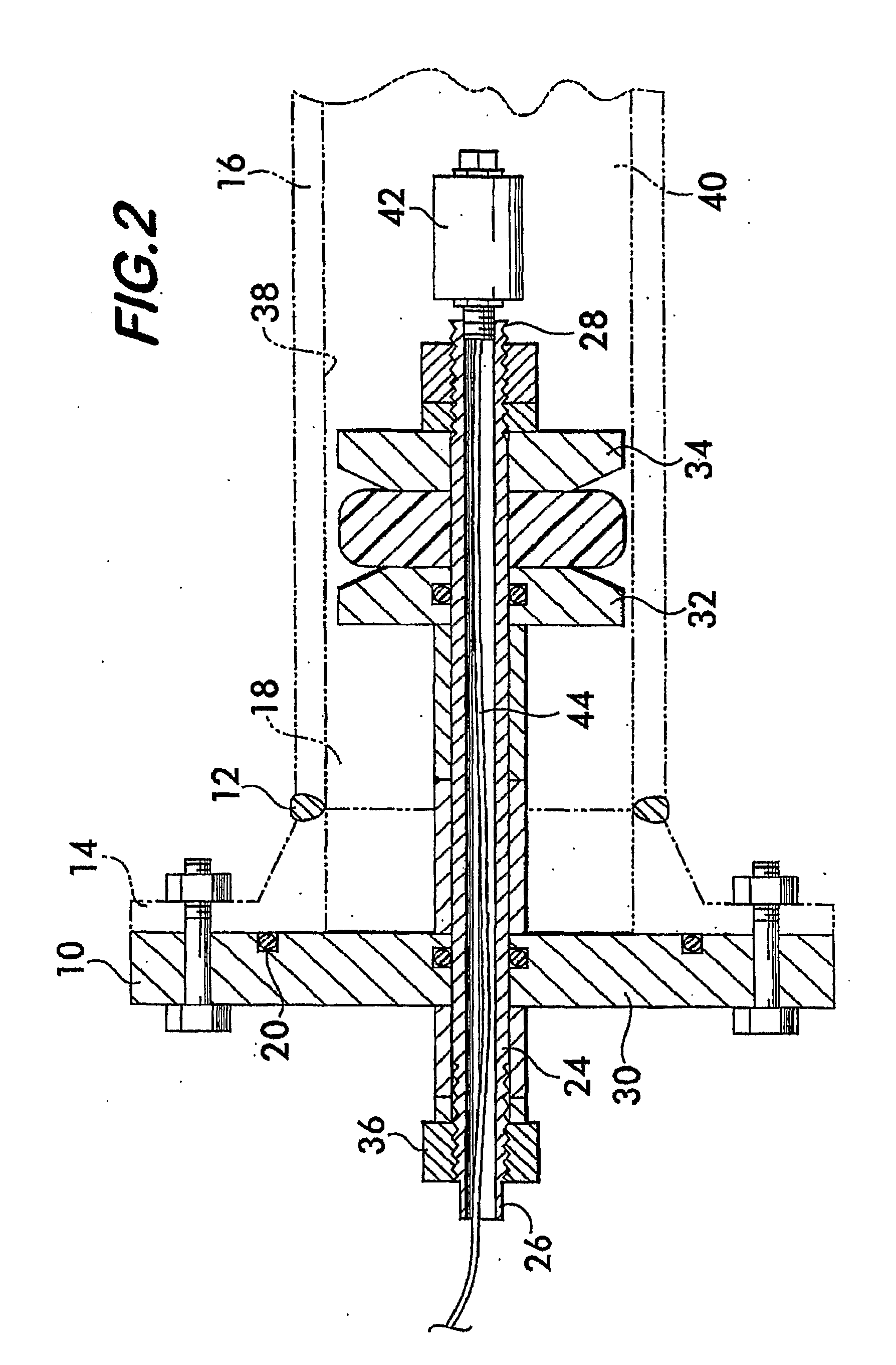
[0020]As the present invention, a flange weld test plug 10 is illustrated in FIGS. 1-3. The test plug 10 is used, for example, in hydraulic pressure and leak testing procedures performed on an annular weld 12 connecting a neck flange 14 to an end of a pipe 16. See FIG. 3. The flange weld test plug 10 is also used during procedures to complete or repair the weld 12 when installing, repairing, or retrofitting the pipe 16 with the neck flange 14. The test plug 10 permits these procedures to be performed without the necessity of filling and pressurizing the entire piping system. Only a section 18 of the pipe 16 between a pair of seals 20 and 22 of the test plug 10 is pressurized.

[0021]The flange weld test plug 10 includes an elongate shaft 24 defining proximal and distal ends, 26 and 28, of the plug 10. A front flange plate 30 is carried on the proximal end 26 of the shaft 24 and is adapted to be connected to the neck flange 14 in a manner forming a fluid-tight seal therebetween. A pair...

second embodiment

[0028]As the present invention, a double-block-and-bleed (DBB) test plug 50 is illustrated in FIGS. 4 and 5. Such a plug 50 can be inserted into an open end of a pipe 52 to test or complete a welded connection 54 that joins a pair of pipes.

[0029]The DBB test plug 50 includes an elongate shaft 56 extending between proximal and distal ends, 58 and 60, of the plug 50. A series of compression elements, or plates, 62 are located adjacent the distal end 60 of the plug 50. A mechanism, such as a threaded fastener or nut 64, provided on the proximal end 58 of the shaft 56 is capable of being advanced or retracted on the shaft 56 to result in the series of compression elements 62 to advance or retract relative to one another. Separate flexible elastic annular seals 66 and 68 are located at longitudinally spaced positions on the shaft 56 and are sandwiched by the series of compression elements 62. Accordingly, when the compression plates, 32 and 34, are advanced or retracted relative to one a...

third embodiment

[0034]As the present invention, a hydrostatic or high pressure test plug 90 is illustrated in FIGS. 6 and 8. The test plug 90 is used to seal the open end of a pipe 92 to enable a pressure test to be run on the pipe 92 and / or an entire piping system. The hydrostatic test plug 90 includes an annular elastic seal 94 capable of being axially compressed so that it expands radially into sealing engagement with an inner peripheral surface 96 of the pipe 92. A portion 98 of the pipe 92 extending behind the seal 94 is pressurized and tested.

[0035]The test plug 90 includes a shaft 100 that carries an annular front wall 102 adjacent a proximal end 104 of the plug 90 and a rear compression washer 106 adjacent a distal end 108 of the plug 90. A cone-shaped or frustoconical washer 110 is supported on the shaft 100 intermediate the annular wall 102 and compression washer 106. A set of segmented grippers 112 is supported on a tapered section 114 of the cone-shaped washer 110 and bridges the gap be...


PUM


Abstract

A test plug assembly (10, 50, 90) includes a shaft (24, 56, 100) on which an annular elastic seal (22, 68, 94) and compression elements (32, 34, 62, 106, 110) are mounted. The compression elements (32, 34, 62, 106, 110) confront opposite axial sides of the annular seal (22, 68, 94) and are movable relative to one another for axially compressing and radially expanding the seal (22, 68, 94) into fluid-tight sealing engagement with an inner peripheral wall (38, 70, 96) of a pipe (16, 52, 92). A transducer (42, 80, 122) is mounted on the distal end of the shaft (24, 56, 100) and measures a condition within the pipe (16, 52, 92) at a location beyond the seal (22, 68, 94). As one example, the transducer (42, 80, 122) is a temperature compensation pressure transducer for obtaining pressure measurements within the downstream portion of the pipe (16, 52, 92) beyond the test plug (10, 50, 90). The transducer (42, 80, 122) produces electrical signals and is in communication with a control unit (982) located externally of the pipe (16, 52, 92). The control unit (982) converts the electronic signals of the transducer (42, 80, 122) for driving a display apparatus (983) to provide visible or audible information and/or warning signals concerning the measurements. The control unit (982) is responsive to transducer signals for automatically terminating welding of a pipe when the signals indicate that pressure at the distal end of the shaft (24, 56, 100) beyond the seal (22, 68, 94) is at a prescribed undesired level.

Description

BACKGROUND OF THE INVENTION[0001]The present invention relates to test plugs for sealing open ends of pipes, tubes, pressure vessels and the like and / or for forming seals at locations on opposite sides of welded-connections, and more particularly, the present invention relates to a test plug that permits conditions within the pipe beyond the test plug to be monitored.[0002]Examples of test plugs for testing pipes, tubes, vessels, and the like for leaks are disclosed by U.S. Pat. Nos. 6,675,634 B2 and 5,676,174 issued to Berneski, Jr. et al., International PCT Publication No. WO 00 / 03172 of Berneski, Jr. et al., and 5,797,431 issued to Adams. In addition, see U.S. Pat. No. 5,024,079 issued to Dufort for an example of a flange weld test plug and U.S. Pat. Nos. 5,844,127 and 6,131,441 issued to Berube et al. for examples of so-called double-block-and bleed, or dumbbell, test plugs.[0003]Conditions, such as pressure, within a section of pipe located beyond the distal end of a test plug ...

Claims


Application Information

Patent Timeline
Patent Type & Authority Applications(United States)
IPC IPC(8): G01M3/04
CPCG01M3/022
Inventor PADDEN, FREDERICK W.
Owner EST GROUP
Why Eureka
Try Eureka