High-lift device, wing, and noise reduction structure for high-lift device

a high-lift device and noise reduction technology, applied in the direction of fuselage, airflow influencer, fuselage insulation, etc., can solve the problems of structural (spatial) problems, increased airframe weight of the aircraft, and structural problems, so as to suppress the occurrence of aerodynamic noise, reduce noise, and suppress the collision

Active Publication Date: 2010-04-08
MITSUBISHI HEAVY IND LTD
View PDF14 Cites 22 Cited by
  • Summary
  • Abstract
  • Description
  • Claims
  • Application Information

AI Technical Summary

Benefits of technology

[0056]Since the airflow control part can suppress the turbulence colliding against the airflow control part, it is possible to suppress the occurrence of aerodynamic noise caused by turbulence compared with a case where the airflow control part is not provided.
[0057]With the high-lift device according to the first aspect of the present invention, the wing according to the second aspect thereof, and the noise reduction structure for a...

Problems solved by technology

There is less extra space inside the main wing or the like, leading to a structural (spatial) problem in disposing the mechanism.
There is a structural (sp...

Method used


Image

  • High-lift device, wing, and noise reduction structure for high-lift device
  • High-lift device, wing, and noise reduction structure for high-lift device
  • High-lift device, wing, and noise reduction structure for high-lift device

Examples


first embodiment

[0095]A wing according to a first embodiment of the present invention will be described with reference to FIGS. 1 to 15.

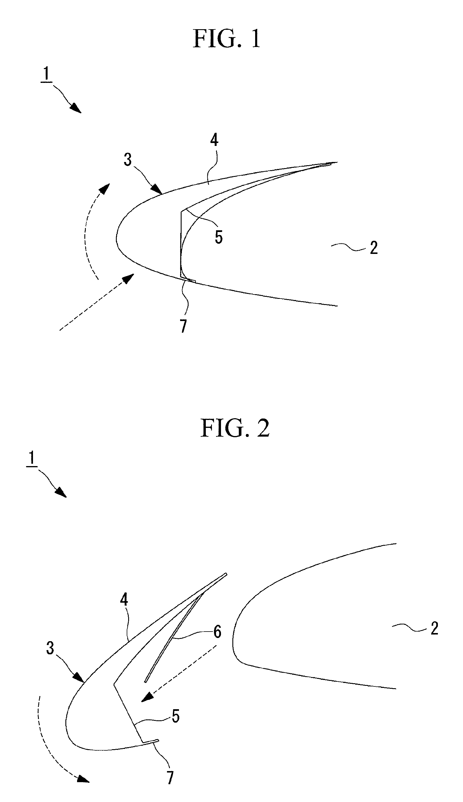
[0096]FIG. 1 is a view for explaining an outline of the wing according to this embodiment and is a partial enlarged view for explaining a state where a slat is retracted. FIG. 2 is a partial enlarged view for explaining a state where the slat is extended in the wing shown in FIG. 1.

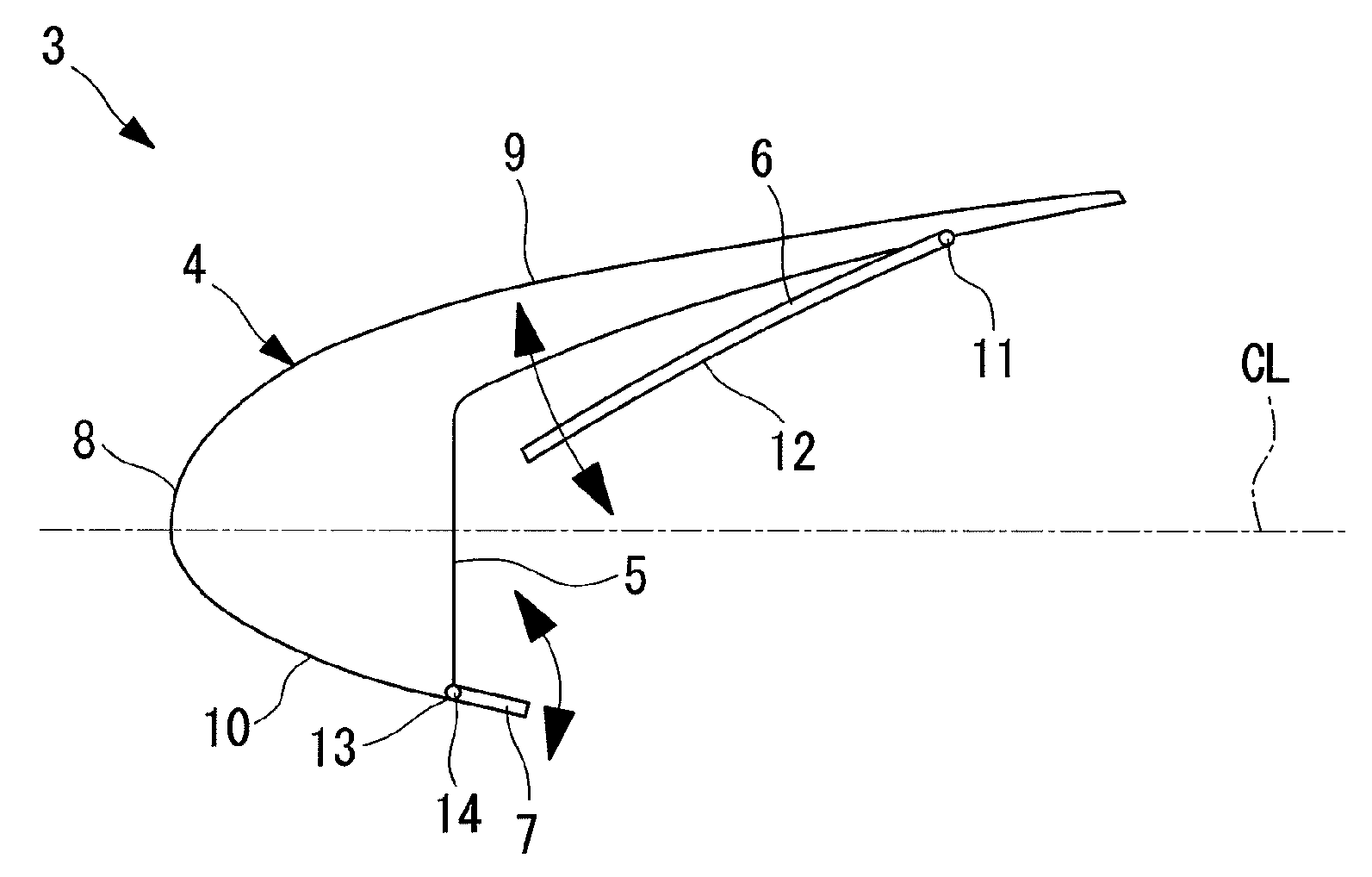
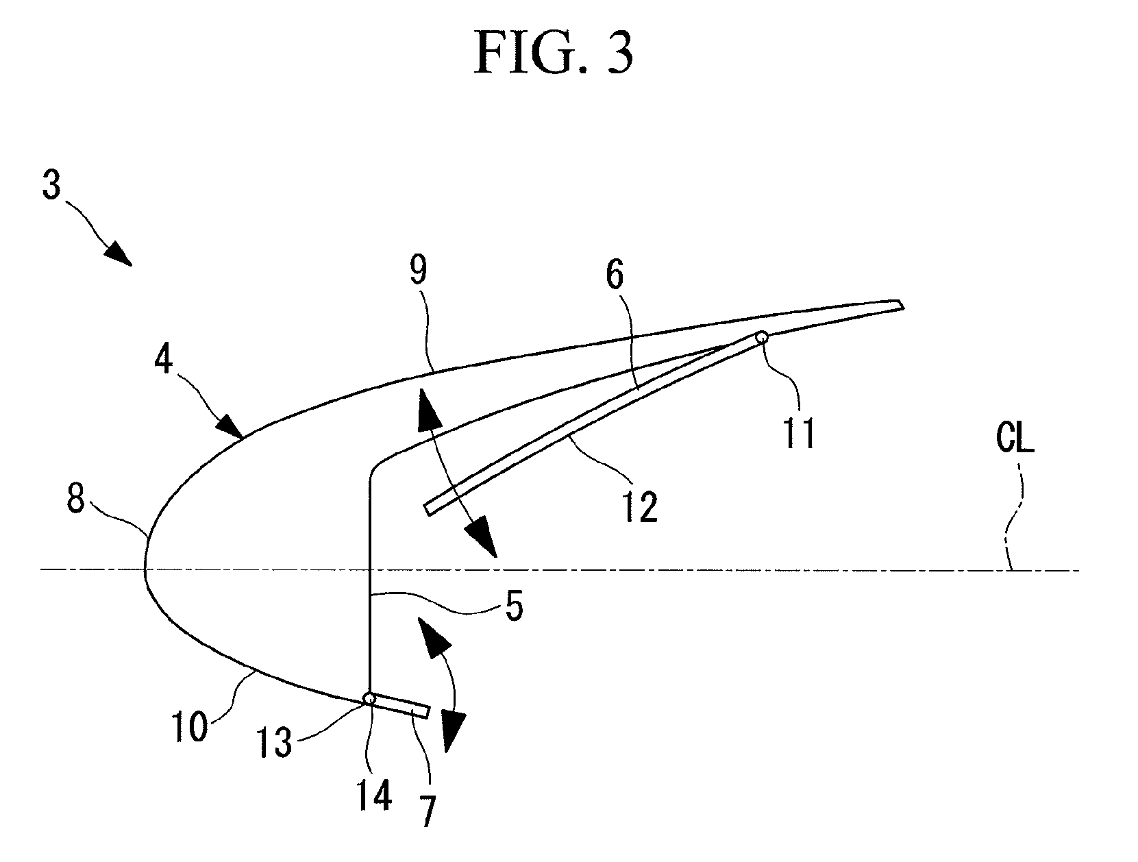
[0097]As shown in FIGS. 1 and 2, a wing 1 includes a main wing 2 and a slat (high-lift device) 3.

[0098]The main wing 2 is a member constituting the wing 1 together with the slat 3. The main wing 2 is formed to have an airfoil section to realize required aerodynamic characteristics when the slat 3 is retracted to serve as the wing 1 and when the slat 3 is extended to serve as the paired main wing 2 and slat 3.

[0099]The slat 3 is disposed at the leading edge of the main wing 2. A drive mechanism (not shown) that retracts and extends the slat 3 is provided inside the main wing 2.

[0100]Note ...

second embodiment

[0180]Next, a second embodiment of the present invention will be described with reference to FIGS. 16 to 20.

[0181]Although the basic structure of a wing of this embodiment is the same as that of the first embodiment, the structure of a noise reduction structure in a slat is different from that of the first embodiment. Therefore, in this embodiment, only the slat and the components surrounding it will be described with reference to FIGS. 16 to 20, and a description of the main wing etc. will be omitted.

[0182]FIG. 16 is a cross-sectional view for explaining the structure of the slat according to this embodiment. FIG. 17 is a cross-sectional view for explaining the structure of an airflow control part shown in FIG. 16. FIG. 18 is a cross-sectional view for explaining a structure for mounting the airflow control part shown in FIG. 17 to the slat.

[0183]Note that the same reference symbols are given to the same components as those of the first embodiment, and a description thereof will be...

third embodiment

[0219]Next, a third embodiment of the present invention will be described with reference to FIG. 24.

[0220]Although the basic structure of a wing of this embodiment is the same as that of the second embodiment, the structure of a noise reduction structure in a slat is different from that of the second embodiment. Therefore, in this embodiment, only the slat and the components surrounding it will be described with reference to FIG. 24, and a description of the main wing etc. will be omitted.

[0221]FIG. 24 is a cross-sectional view for explaining the structure of an airflow control part according to this embodiment.

[0222]Note that the same reference symbols are given to the same components as those of the second embodiment, and a description thereof will be omitted.

[0223]As shown in FIG. 24, the slat 3 of a wing 201 includes the slat main body 4, the cove 5, and an airflow control part (noise reduction structure) 206.

[0224]The airflow control part 206 suppresses the turbulence.

[0225]The...


PUM


Abstract

The present invention provides high-lift devices, wings, and noise reduction structures for the high-lift devices capable of suppressing the occurrence of aerodynamic noise while restricting an increase in airframe weight. A high-lift device includes: a slat main body (4) that is disposed so as to be able to extend from and retract into a main wing; a concave part (5) that is formed on the slat main body (4) at a location that faces the main wing, so as to be able to accommodate at least a part of a leading edge of the main wing; and an airflow control part (6) that is disposed at an area in the concave part (5) facing an upper surface of the main wing, that is accommodated between the main wing and the concave part when the slat main body (4) is retracted into the main wing, and that suppresses turbulence colliding against the area in the concave part (5) facing the upper surface of the main wing when the slat main body (4) is extended from the main wing.

Description

TECHNICAL FIELD[0001]The present invention relates to high-lift devices, wings, and noise reduction structures for high-lift devices that are suitable, for example, for suppressing the occurrence of aerodynamic noise.BACKGROUND ART[0002]Noise generated by aircraft at the time of takeoff and landing is a large problem for the environment around airports. This noise includes engine noise and aerodynamic noise generated from high-lift devices (such as, slats and flaps), the undercarriage, etc.[0003]Since the high-lift devices, which are one of the sources of the above-mentioned noise, are used to obtain aerodynamic characteristics required at the time of takeoff and landing of the aircraft, they are designed with an emphasis on their aerodynamic characteristics, whereas noise reduction is not taken into consideration.[0004]However, since the noise is a large problem as described above, efforts have been made to reduce the noise of the high-lift devices as well. For example, technologie...

Claims


Application Information

Patent Timeline
IPC IPC(8): B64C9/24B64C23/00
CPCB64C9/24B64C2009/143
Inventor HIRAI, MAKOTOMAEDA, ICHIRO
Owner MITSUBISHI HEAVY IND LTD
Why Eureka
Try Eureka