Biological sample temperature control system and method

a biological sample and temperature control technology, applied in the field of biological sample temperature control system and method, can solve the problems of affecting the evaluation and imaging of the site, affecting the chemical reaction or binding event, and affecting the effect of reagent temperature changes on chemical reactions or binding events,

Inactive Publication Date: 2010-04-08
ILLUMINA INC
View PDF43 Cites 43 Cited by
  • Summary
  • Abstract
  • Description
  • Claims
  • Application Information

AI Technical Summary

Benefits of technology

[0005]The present invention provides a novel approach for controlling the temperature of biological samples, for example, on a support structure. In embodiments wherein the support structure is present in a detection system, the approach for controlling sample temperature can further provide control of the temperature of the detection system, in particular the region of the detection system where the support structure or biological sample resides. Accordingly, the invention provides a detection

Problems solved by technology

This may prove problematic if the temperature changes become too great in that the physical structures may become susceptible to contraction, expansion, and other forms of distortion.
If any of these types of distortion become too great, the evaluation and imaging of the sites may be compromised in that the sites may either not remain in the same locat

Method used


Image

  • Biological sample temperature control system and method
  • Biological sample temperature control system and method
  • Biological sample temperature control system and method

Examples


Embodiment Construction

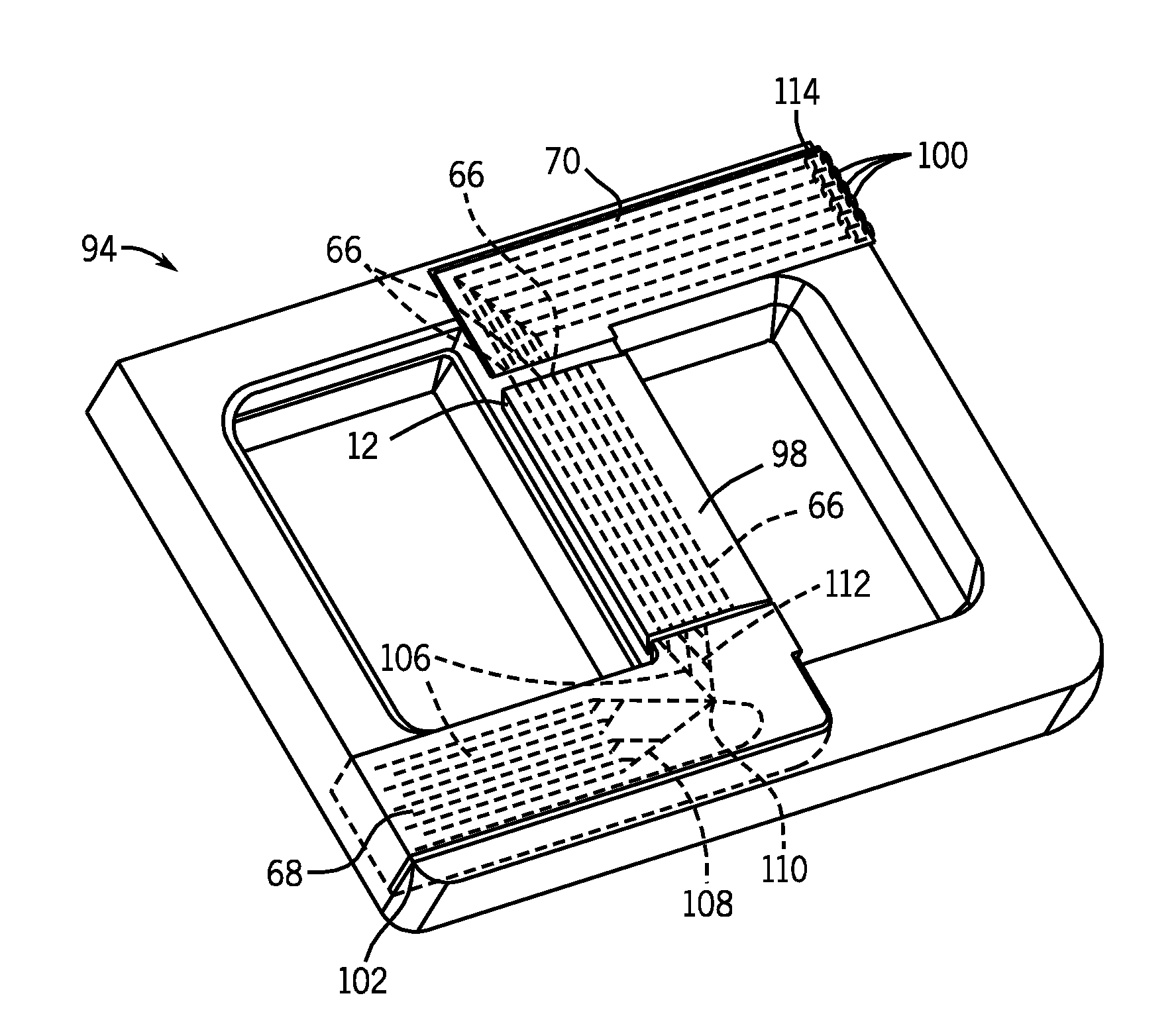
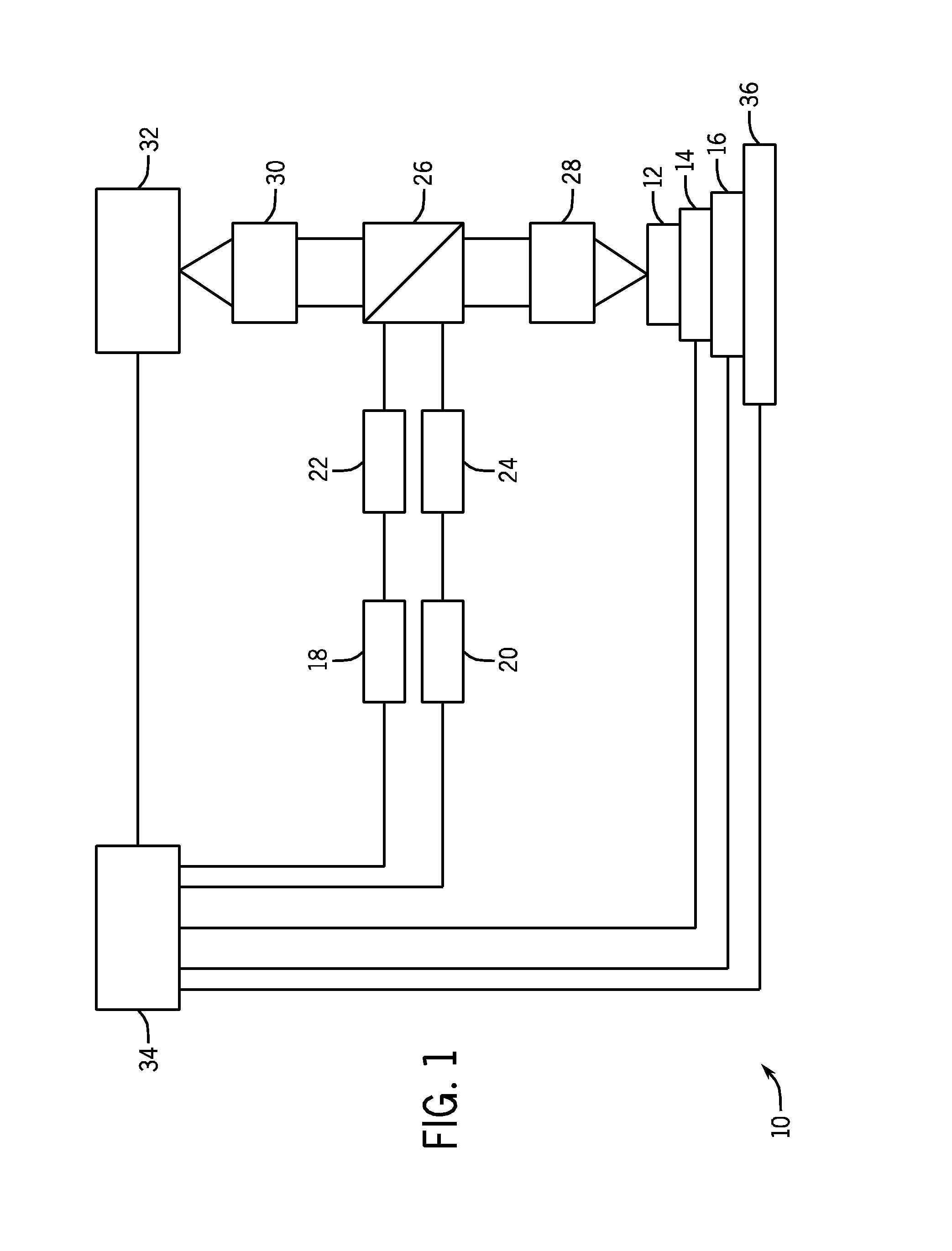
[0032]Turning now to the drawings, and referring first to FIG. 1, a biological sample imaging system 10 is illustrated diagrammatically. The biological sample imaging system 10 is capable of imaging biological components within a support structure 12. The support structure 12 may, for instance, be a flow cell with an array of biological components on its interior surfaces through which reagents, flushes, and other fluids may be introduced, such as for binding nucleotides or other molecules to the sites of biological components. The support structure 12 may be manufactured in conjunction with the present techniques or the support structure 12 may be purchased or otherwise obtained from a separate entity. Fluorescent tags on the probes or target molecules that bind to the probes may, for instance, include dyes that fluoresce when excited by appropriate excitation radiation. Assay methods that include the use of fluorescent tags and that can be used in an apparatus or method set forth ...


PUM


Abstract

The present invention provides a novel approach for controlling the temperature of biological samples on a support structure. The support structure may, for instance, be a flow cell through which a reagent fluid is allowed to flow and interact with biological samples. A thermoelectric heat exchange device, such as a Peltier device, may be used to heat or cool the biological samples on the support structure. In addition, a fluid circulating heat exchange device, such as a water heating or cooling system, may be used to heat or cool the thermoelectric heat exchange device. In general, the support structure may be located on top of the thermoelectric heat exchange device which, in turn, may be located on top of the fluid circulating heat exchange device. The thermoelectric heat exchange device and fluid circulating heat exchange device may be integrated into a holder bench which may be part of a station within an imaging processing system. The holder bench may be configured to hold multiple support structures at a time. In addition, the support structures may be configured to be evaluated and imaged using both epifluorescent and total internal reflection (TIRF) excitation techniques.

Description

CROSS REFERENCE TO RELATED APPLICATIONS[0001]This application is a Non-Provisional of U.S. Provisional Patent Application No. 61 / 103,411, entitled “Biological Sample Temperature Control System and Method,” filed Oct. 7, 2008, which is herein incorporated by reference.BACKGROUND[0002]The present invention relates generally to the field of evaluating and imaging biological samples. More particularly, the invention relates to a technique for controlling the temperature of biological samples on a support structure.[0003]There are an increasing number of applications for imaging of biological samples on a support structure. For instance, these support structures may include deoxyribonucleic acid (DNA) and ribonucleic acid (RNA) probes that are specific for nucleotide sequences present in genes in humans and other organisms. Individual DNA or RNA probes may be attached at specific locations in a small geometric grid or array on the support structure. Depending upon the technology employed...

Claims


Application Information

Patent Timeline
IPC IPC(8): C40B30/00C40B60/12
CPCB01L3/502715B01L7/00B01L7/525B01L2300/021B01L2300/0816B01L2300/0861C40B60/12B01L2300/0867B01L2300/0883B01L2300/168B01L2300/1822B01L2300/185B01L2300/0864
Inventor BUERMANN, DALE
Owner ILLUMINA INC
Why Eureka
Try Eureka