Dispensing device for pressurized containers for the application of cryogenic coolant

a technology of cryogenic coolant and dispensing device, which is applied in the field of new dispensing device for pressurized containers for the application of cryogenic coolant, can solve the problems of affecting the operation of the operator or the patient, requiring more complex and expensive preparation and conservation processes, and wasting materials, so as to prevent accidental fluid leakage

Inactive Publication Date: 2010-04-08
SIXTEM LIFE SRL
View PDF7 Cites 19 Cited by
  • Summary
  • Abstract
  • Description
  • Claims
  • Application Information

AI Technical Summary

Benefits of technology

[0022]These and other direct and complementary objects have been achieved through the construction of a new dispensing device for pressurized containers with manual valve for the application of cryogenic cooling gas in cryotherapy, comprising a dispenser body with a built-in and integral tube, in which it is possible to partially insert a removable cylindrical applicator pad or filter, suited to absorb and covey the coolant, wherein a safety activator cap or plug is suited to close the dispenser body, thus preventing accidental fluid leakages, or to open the valve causing the controlled delivery of the fluid that, conveyed through said tube, is immediately absorbed by said pad or filter.
[0023]Said activator cap comprises a casing suited to be positioned to close the dispenser body, to which it can be removably connected, and an inner channel, integral with the upper part of the cap, suited to house said tube or duct of the dispenser body.
[0024]The cylindrical wall of said inner channel of the cap comprises, on its lower edge, one or more teeth or projections suited to be inserted in corresponding through slots or holes made in said dispenser body.
[0025]A downward pressure exerted on said cap—correctly positioned—causes said teeth or projections to be completely or partially inserted in said slots, so that they rest on an element, hereinafter called valve-opening element, positioned between said dispenser body and the upper edge of the container, connected to said valve.
[0026]The pressure exerted on said valve-opening element causes said valve to open, which makes the fluid flow out through said tube or duct integral with the dispenser body.
[0027]The pad or filter partially inserted in said tube absorbs the fluid and conveys it to the top, getting completely soaked with said fluid.

Problems solved by technology

The use of other fluids like carbon dioxide and nitrous oxide is also known, which however require more complex and expensive preparation and conservation processes.
Said applicator pad soaked with coolant is applied to the area to be treated, which thus freezes, causing the breakage of the cellular membranes and the successive detachment of the epidermis from the dermis.
One of the drawbacks of by the known devices lies in that the coolant may be spread out in an uncontrolled manner, for example during application or removal of the tube, thus causing a waste of material and above all a risk of injuries or lesions to the operator or the patient.
Furthermore, it is necessary for the operator to act rapidly when dispensing the coolant, in order to prevent its temperature to increase excessively compared to the optimal values, which would reduce the effectiveness of the treatment.
The use of the known containers, which comprise removable parts like tubes and pads, often makes the operation rather complex and for this reason the operator works less rapidly.

Method used


Image

  • Dispensing device for pressurized containers for the application of cryogenic coolant
  • Dispensing device for pressurized containers for the application of cryogenic coolant
  • Dispensing device for pressurized containers for the application of cryogenic coolant

Examples


Embodiment Construction

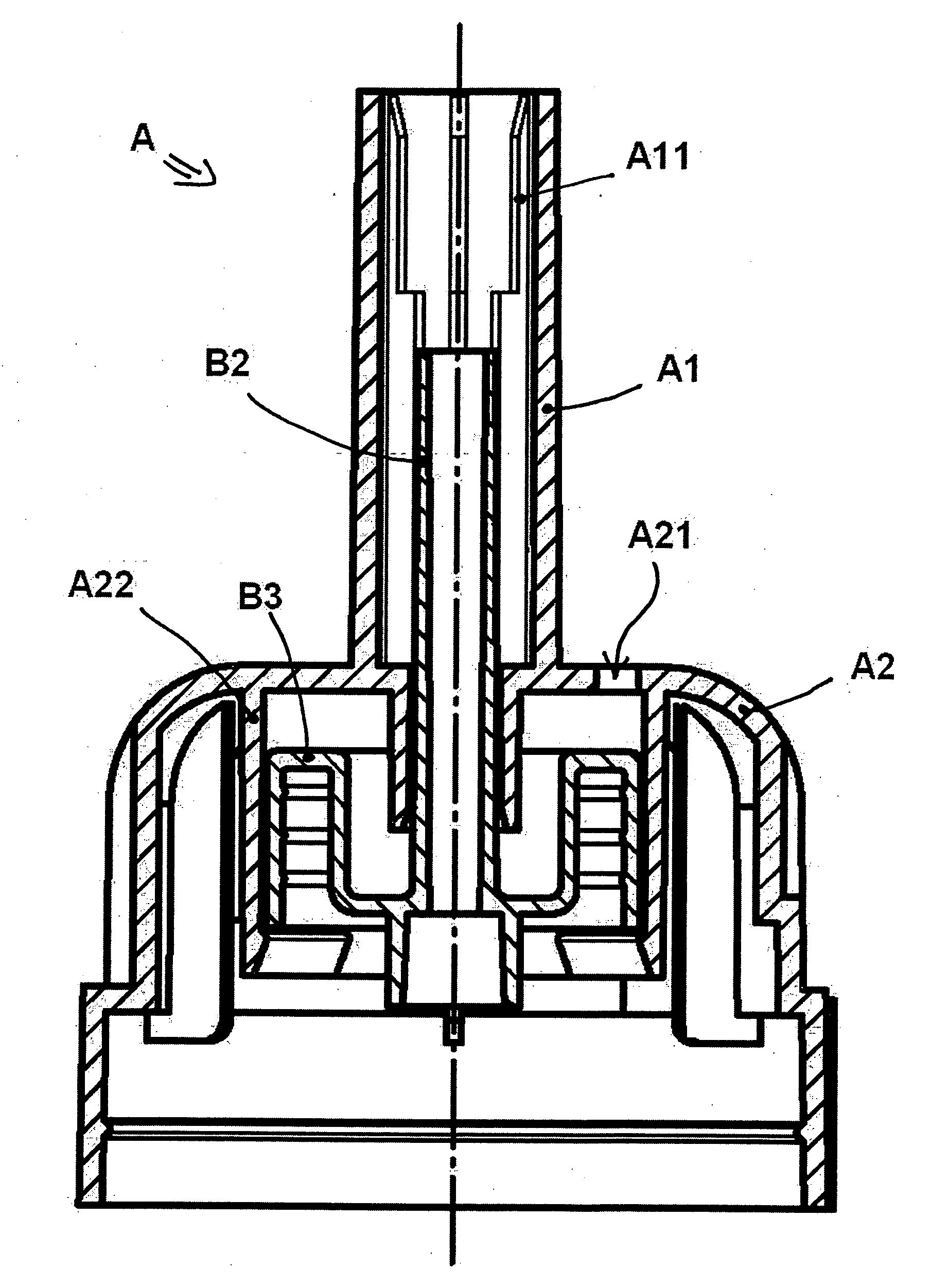
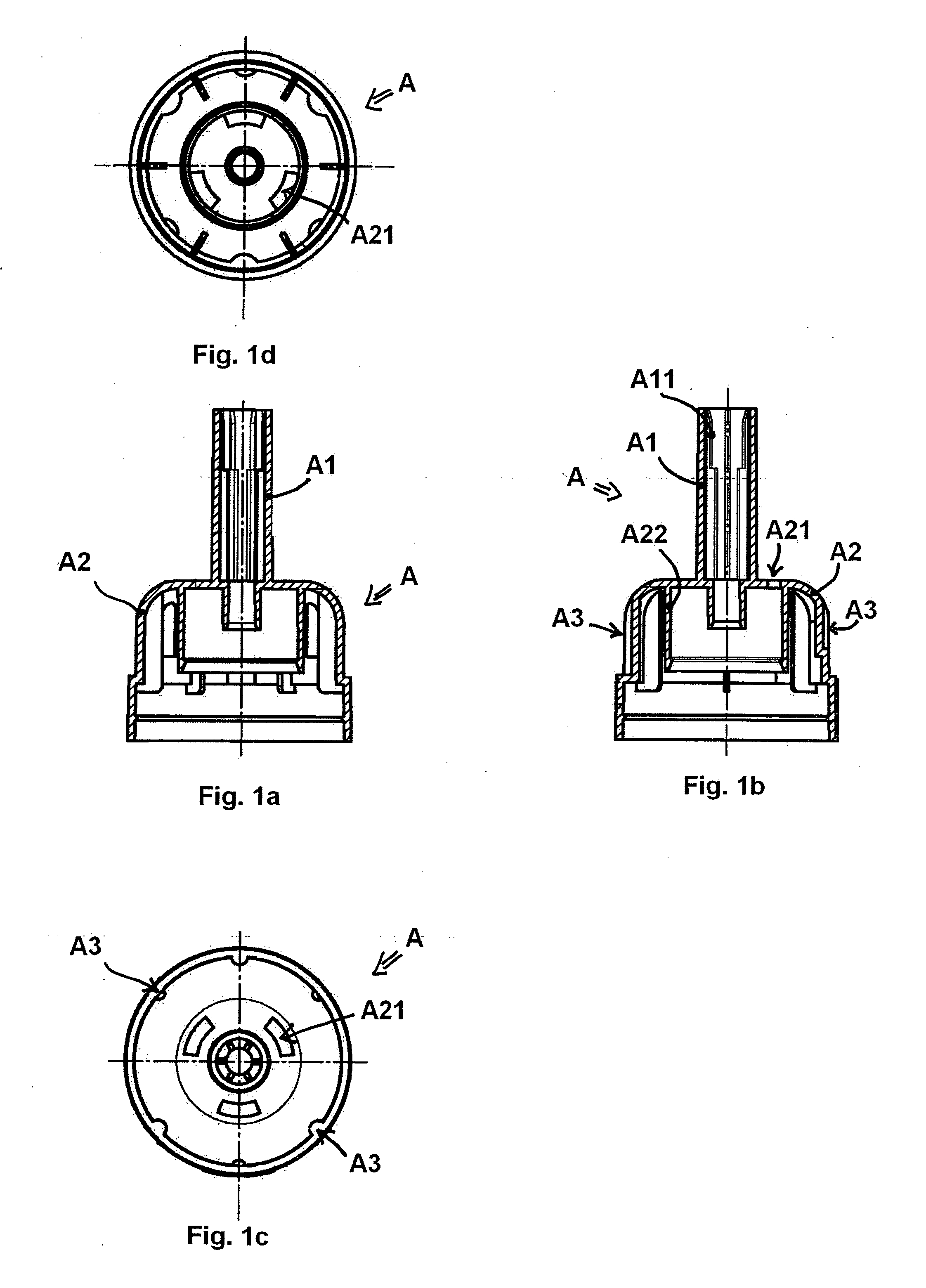
[0041]Referring to the figures, the new dispensing device can be integrally applied to pressurized containers (C) equipped with a manual valve (C1), of the sprayer type, and comprises a dispenser body (A) suited to be fixed to said container (C).

[0042]Said dispenser body (A) substantially comprises a convex or dome-shaped part (A2) suited to contain the upper end of the container and at least one duct or tube (A1) integral with and built in said cupola-shaped part (A2) for the outflow of the coolant contained in the container (C).

[0043]The inside of said tube (A1) is shaped in such a way as to comprise ribs (A1) suited to hold at least one cylindrical pad or filter (S) partially inserted in it.

[0044]In the preferred embodiment, in order to guarantee effective absorption and conveyance of the coolant, said cylindrical pad or filter (S) is made if polyurethane S518, with a diameter of approximately 7 mm and a length of 18 mm.

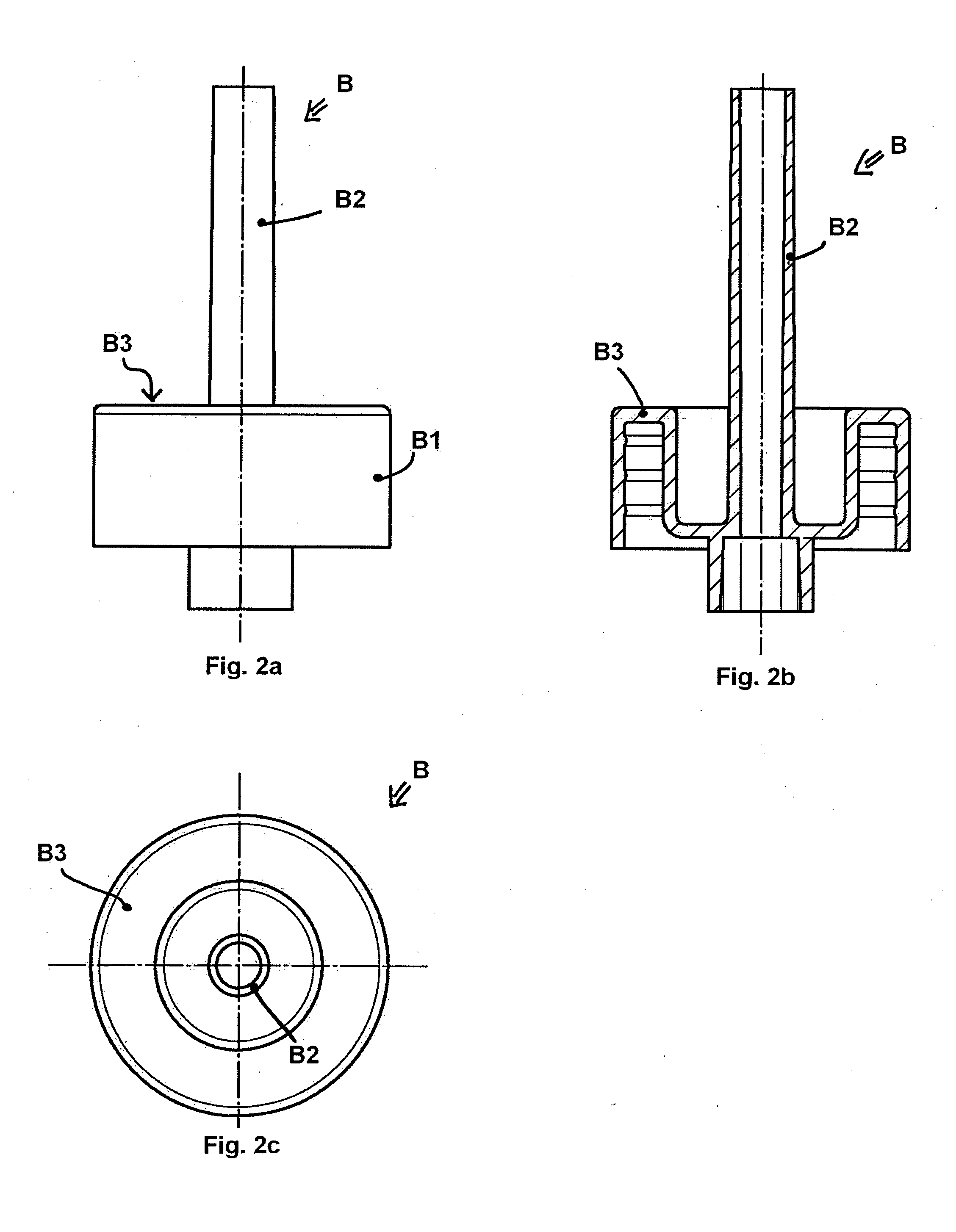
[0045]A valve-opening element (B) is interposed and fixed be...


PUM


Abstract

The invention relates to a new dispensing device for pressurized containers of coolants for cryotherapy, with a manual opening/closing valve, which includes a dispenser body suited to be permanently fixed to said container, a valve-opening element and a cap with teeth resting against said valve-opening element to cause the opening of the valve. In one embodiment, at least one tube or duct for application of the coolant, at one end of which at least one applicator pad or filter is partially and removably inserted, is permanently built in and integral with said dispenser body.

Description

FIELD OF THE INVENTION[0001]The present invention concerns medical devices for cryotherapy in the treatment of skin lesions and warts, and in particular concerns a new dispensing device for pressurized containers for the application of cryogenic coolant.BACKGROUND OF THE INVENTION[0002]Cryotherapy is a therapeutic process, in which very cold fluids are used for the local treatment of skin lesions like warts or other less or more serious skin diseases.[0003]The controlled and punctual application of coolant to the lesion causes the freezing of the intracellular water and the alteration of proteins and enzymes causing, over the therapeutic application and successive thawing time, the detachment of the epidermis from the dermis without damaging the latter.[0004]The advantages offered by cryotherapy are therefore numerous. First of all, anesthesia of the area to be treated is not usually required and furthermore, in most cases, no scars appear and there is no need for further post-opera...

Claims


Application Information

Patent Timeline
Patent Type & Authority Applications(United States)
IPC IPC(8): A61B18/02
CPCA61B18/0218A61M35/00B65D83/40B65D83/285B65D83/22
Inventor CITTERIO, MAUROOTTANELLI, LUCIANO
Owner SIXTEM LIFE SRL
Why Eureka
Try Eureka