Apparatus and Method for Detecting End-of-Fill at Clutch in Automatic Transmission

a technology of automatic transmission and clutch, which is applied in the direction of mechanical apparatus, mechanical actuated clutch, instruments, etc., can solve the problems of engine speed, controllers may inadvertently “underfill” or “overfill” the clutch, prolonging the transmission operation life expectancy, etc., and achieves high fluid pressure

Inactive Publication Date: 2010-04-08
GM GLOBAL TECH OPERATIONS LLC
View PDF36 Cites 16 Cited by
  • Summary
  • Abstract
  • Description
  • Claims
  • Application Information

AI Technical Summary

Benefits of technology

[0014]In accordance with another aspect, detecting if an aberration occurs in the active current draw includes determining a change in instantaneous velocity of the solenoid armature. To this regard, detecting if an aberration occurs also includes determining if the change in instantaneous velocity is greater than a threshold change in armature velocity. Ideally, determining the change in instantaneous velocity is based upon certain solenoid parameters, which include, for example, the inductance, slope of inductance as a function of armature position, and resistance of the solenoid.
[0015]According to yet another embodiment of the present invention, a control apparatus for regulating activation of a hydraulic clutch in an automatic transmission is provided. The control apparatus includes a variable force solenoid (VFS) having a coil in operative communication with a transmission current source. The solenoid also includes a spool that operates to selectively fluidly communicate a pressurized fluid source with the clutch apply volume. An armature is connected to the spool, and circumscribed by the coil, whereby the armature operates to transition between a first and a second position in response to current flowing through the coil. A controller is in operative communication with the solenoid, and operates, at least in part, to control the movement of the armature. A sensor is in operative communication with both the solenoid an...

Problems solved by technology

Detecting end-of-fill at the clutch is extremely critical in controlling automatic transmissions, and prolonging transmission operational life expectancy.
If the proper fill time is not known or accurately estimated, the controller may inadvertently “underfill” or “overfill” the clutch when attempting to modulate clutch pressure to fully engage the clutch.
An “underfill” condition may result in “engine flare”—a sudden spike in engine speed, which leads to quicker wear of the clutch friction materi...

Method used


Image

  • Apparatus and Method for Detecting End-of-Fill at Clutch in Automatic Transmission
  • Apparatus and Method for Detecting End-of-Fill at Clutch in Automatic Transmission
  • Apparatus and Method for Detecting End-of-Fill at Clutch in Automatic Transmission

Examples


Embodiment Construction

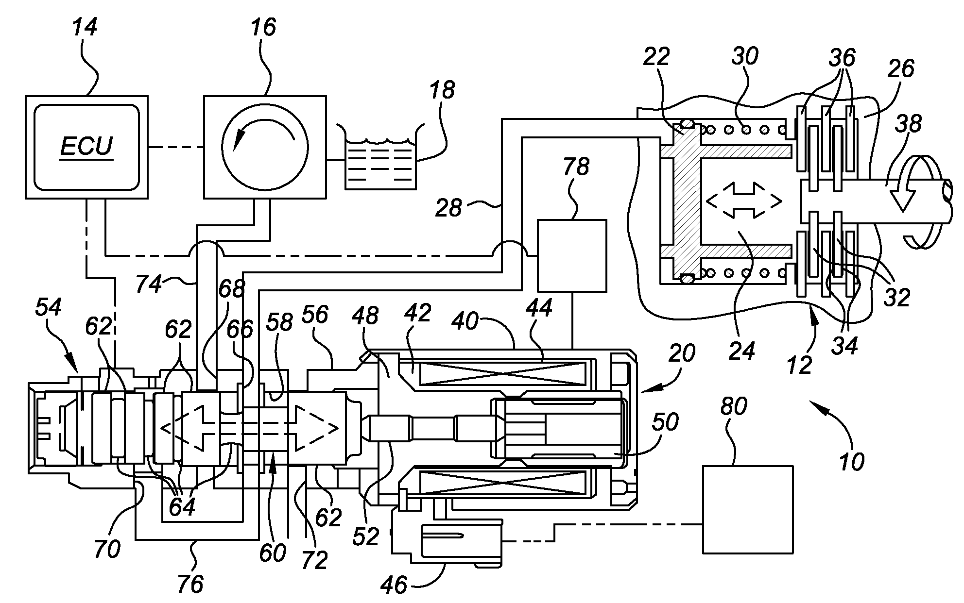
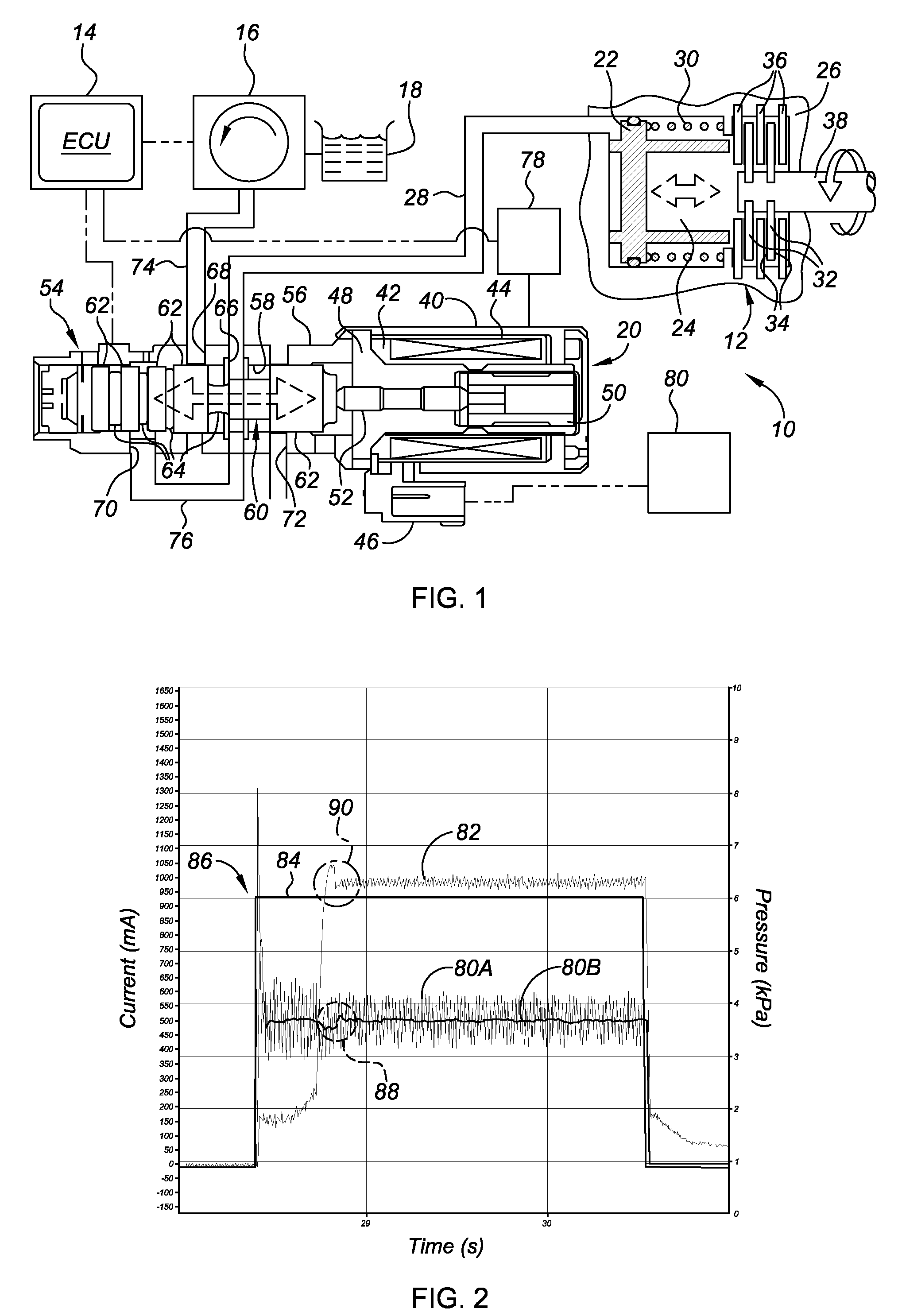
[0022]The present invention is described herein in the context of an electro-hydraulic control system for a multi-ratio automatic transmission. The portion of the electro-hydraulic control system shown in FIG. 1 hereof has been greatly simplified, it being understood that further information regarding the fluid pressure routings and general operation of a power transmission may be found in the prior art. Furthermore, it should be readily understood that FIG. 1 is merely an exemplary application by which the present invention may be incorporated and practiced. Accordingly, the present invention is by no means limited to the particular configuration presented in FIG. 1.

[0023]Referring to the drawings, wherein like reference numbers refer to like components throughout the several views, a portion of an electro-hydraulic control system for a power transmission is schematically illustrated in FIG. 1, and designated generally at 10. The control system 10 (also referred to as “control appa...


PUM


Abstract

An improved method and apparatus for detecting end-of-fill at a hydraulic clutch in an automatic transmission with a variable force solenoid are provided. The method includes: initiating clutch fill mode by commanding a high current to the solenoid whereby a high fluid pressure is delivered to the clutch apply volume; monitoring clutch fill time; determining if the fill time is greater than a threshold fill time; monitoring the current (e.g., actual and filtered) being actively drawn by the solenoid during clutch fill mode in response to the fill time being greater than the threshold fill time; detecting if an aberration occurs in the current; and stopping distribution of fluid to the hydraulic clutch in response to the current aberration. Detecting if an aberration occurs preferably includes determining a change in instantaneous armature velocity, and determining if the change in instantaneous velocity is greater than a threshold change in armature velocity.

Description

TECHNICAL FIELD[0001]The present invention relates generally to motor vehicle powertrains, and more specifically to methods for detecting end-of-fill at a clutch in an automatic transmission, and devices for practicing the same.BACKGROUND OF THE INVENTION[0002]Most automatic transmissions used in contemporary motor vehicles, such as the modern-day automobile, include a number of gear elements, generally in the nature of epicyclic planetary gear sets, for coupling the transmission's input and output shafts. Traditionally, a related number of hydraulically actuated torque establishing devices, such as clutches and brakes (the term “torque transmitting device” used hereinafter to refer to both clutches and brakes), are selectively engageable to activate the aforementioned gear elements for establishing desired forward and reverse speed ratios between the transmission's input and output shafts. The speed ratio is defined as the transmission input speed divided by the transmission output...

Claims


Application Information

Patent Timeline
IPC IPC(8): F16D25/12G06F17/00
CPCF16D48/066F16D2048/0221F16D2500/1026F16H2061/062F16D2500/70414F16H61/061F16D2500/3022
Inventor NEELAKANTAN, VIJAY A.BAI, SHUSHAN
Owner GM GLOBAL TECH OPERATIONS LLC
Why Eureka
Try Eureka