Remote Plasma Apparatus for Manufacturing Solar Cells

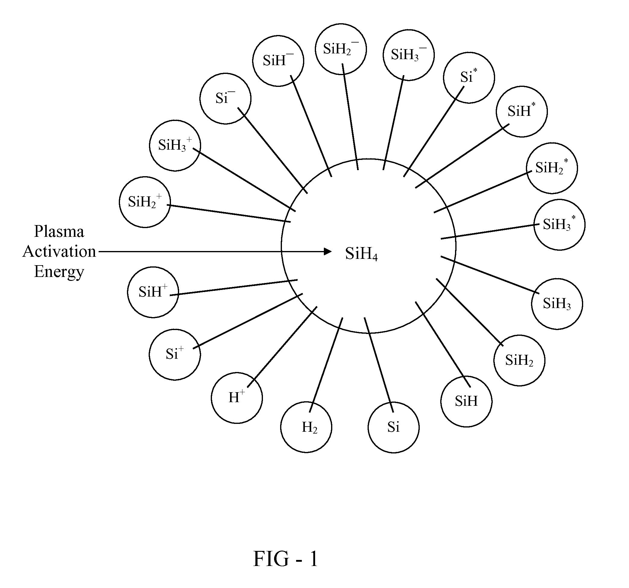
a solar cell and plasma technology, applied in chemical vapor deposition coatings, electric discharge tubes, coatings, etc., can solve the problems of limited deposition rate of prevailing plasma deposition techniques, structural defects such as dangling bonds, strained bonds, and non-tetrahedral bonding distortions, and achieve favorable species distribution effects

Inactive Publication Date: 2010-04-15
OVSHINSKY TECH
View PDF3 Cites 6 Cited by
  • Summary
  • Abstract
  • Description
  • Claims
  • Application Information

AI Technical Summary

Benefits of technology

[0012]This invention provides an apparatus for the plasma or plasma-assisted deposition of thin film materials. The apparatus receives a precursor gas and converts it into a charge-depleted deposition medium that is used in the formation of a thin film material. The charge-depleted deposition medium provides a more favorable distribution of species for forming thin film materials having a low defect concentration.

Problems solved by technology

The deposition rate of prevailing plasma deposition techniques is limited by the high concentration of intrinsic defects that develops in amorphous solar materials as the deposition rate is increased.
The intrinsic defects include structural defects such as dangling bonds, strained bonds, unpassivated surface states, non-tetrahedral bonding distortions, coordinatively unsaturated silicon or germanium.
The structural defects create electronic states in the bandgap of the amorphous semiconductors that detract from solar conversion efficiency by promoting nonradiative recombination processes that deplete the concentration of free carriers generated by absorbed sunlight.
Intrinsic defects are also believed to contribute to degradation of solar cell performance through the Staebler-Wronski effect.
The instant inventor has shown that charged species are generally detrimental to the quality of as-deposited amorphous semiconductors because they promote the creation of defects.
Charged species tend to strike the deposition surface with high kinetic energy and as a result, tend to damage a growing thin film material through bond cleavage.
Unfortunately, the reduced deposition rate impairs the economic competitiveness of the process.

Method used


Image

  • Remote Plasma Apparatus for Manufacturing Solar Cells
  • Remote Plasma Apparatus for Manufacturing Solar Cells
  • Remote Plasma Apparatus for Manufacturing Solar Cells

Examples


Embodiment Construction

[0023]Although this invention will be described in terms of certain preferred embodiments, other embodiments that are apparent to those of ordinary skill in the art, including embodiments that do not provide all of the benefits and features set forth herein and including embodiments that provide positive benefits for high-volume manufacturing, are also within the scope of this invention. Accordingly, the scope of the invention is defined only by reference to the appended claims.

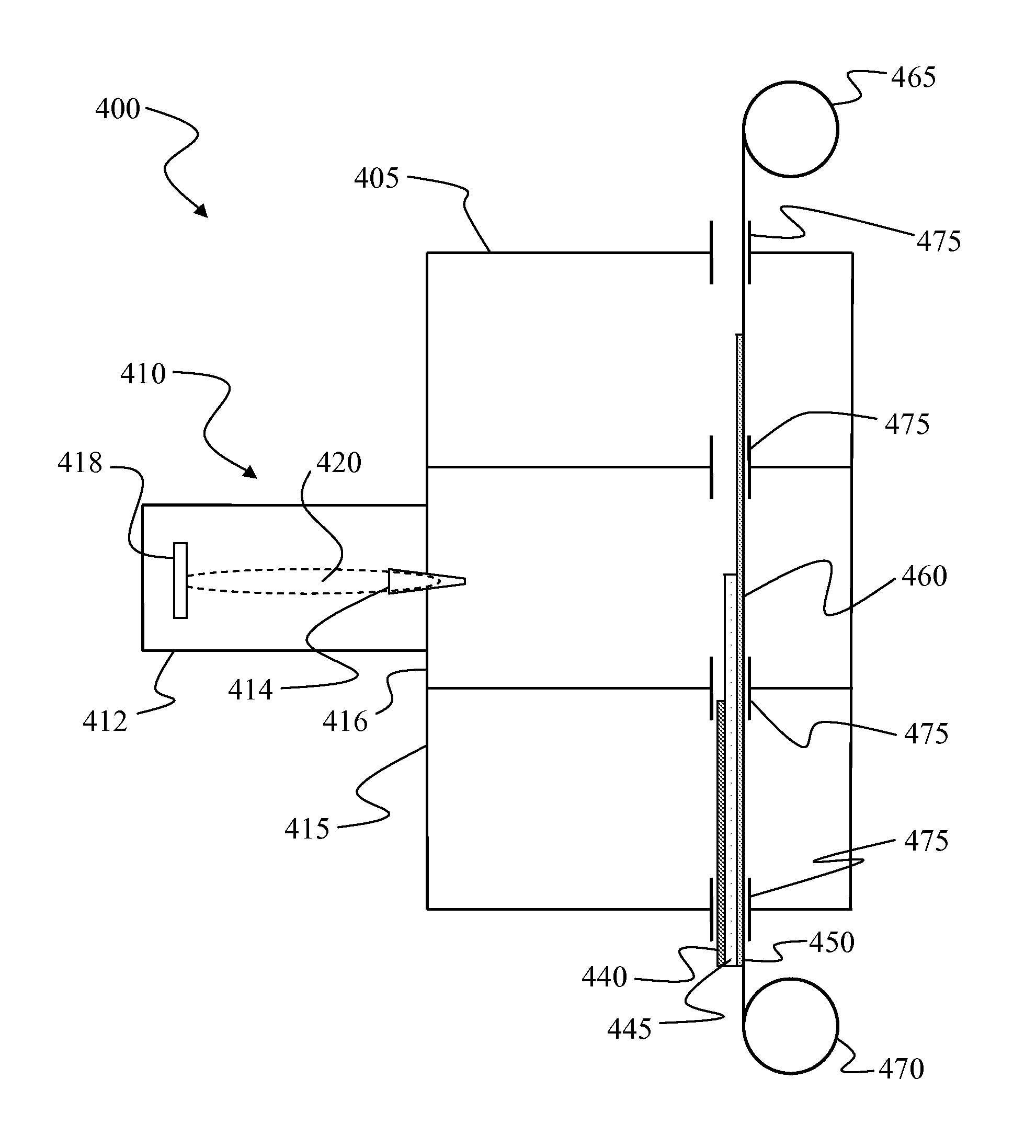
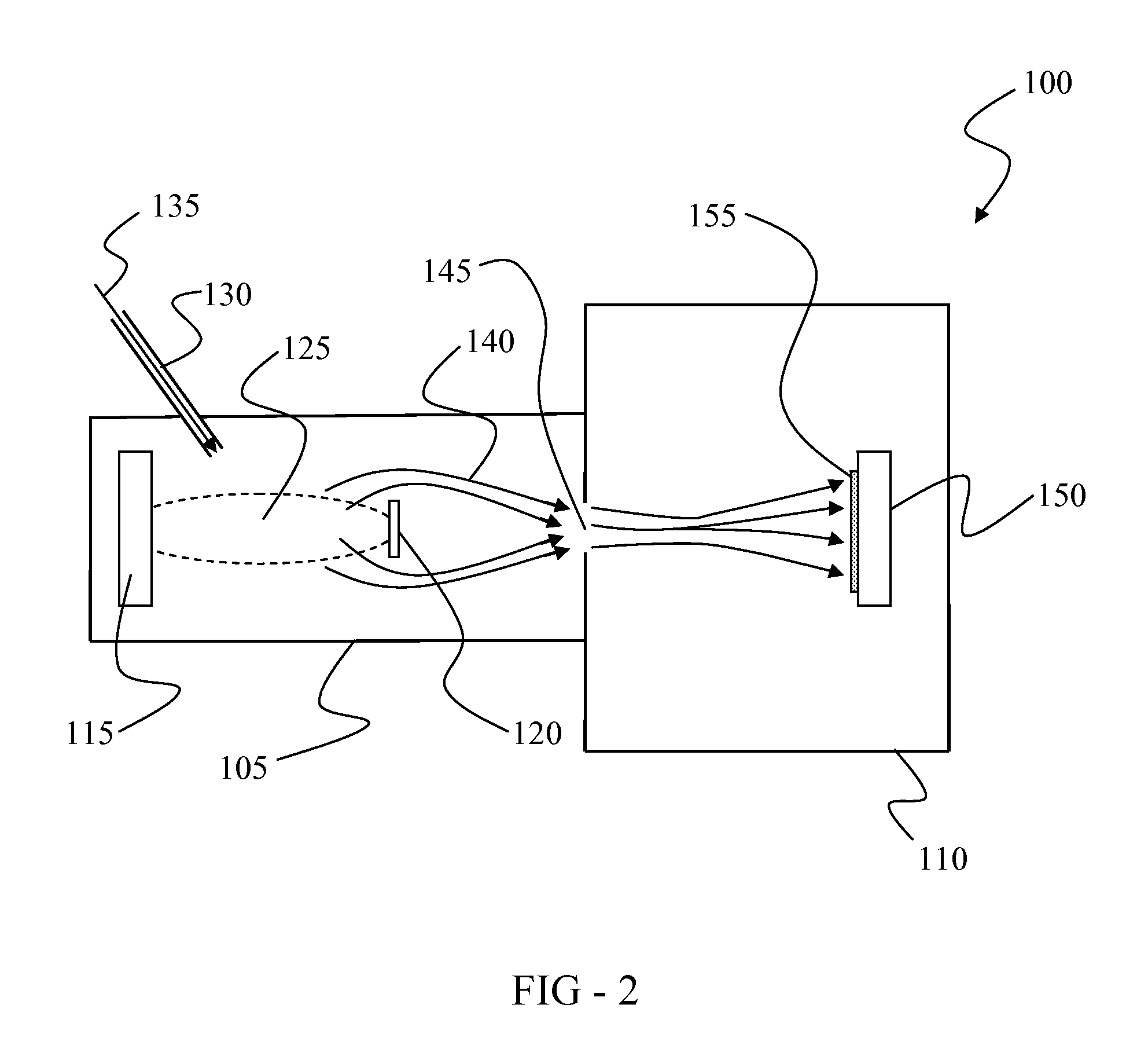
[0024]This invention provides a deposition apparatus for manufacturing thin film materials, including amorphous semiconductors, at high rates of production. The apparatus includes a plasma source remote from the substrate. The remote plasma source generates a plasma external to a deposition chamber, without using the substrate as an electrode for plasma generation. The plasma exits the remote plasma source and is delivered in a state depleted in charged particles (ions and electrons) to a moving substrate for...


PUM

PropertyMeasurementUnit
pressureaaaaaaaaaa
pressureaaaaaaaaaa
semiconductoraaaaaaaaaa

Abstract

A continuous thin film deposition apparatus that includes a remote plasma source. The source forms a plasma from a precursor and delivers a modified form of the plasma as a charge-depleted deposition medium to a deposition apparatus for formation of a thin film material. The thin film may be formed on a continuous web or other moving substrate. The charge-depleted deposition medium may be formed within the remote plasma source and delivered to an operatively coupled deposition apparatus or the charge-depleted deposition medium may form as the plasma exits the remote plasma source. The initial plasma is formed within the remote plasma source and includes a distribution of charged species (electrons and ions). The charge-depleted deposition medium contains a reduced concentration of the charged species and permits deposition of thin film materials having lower defect concentration. In one embodiment, the thin film material is a solar material and the lower defect concentration provides a higher solar conversion efficiency.

Description

RELATED APPLICATION INFORMATION[0001]This application is a continuation in part of U.S. patent application Ser. No. 12 / 209,699, entitled “High Speed Thin Film Deposition via Pre-Selected Intermediate” and filed on Sep. 12, 2008, the disclosure of which is hereby incorporated by reference. This application is also a continuation in part of U.S. patent application Ser. No. 12 / 316,417, entitled “Thin Film Deposition via a Spatially-Coordinated and Time-Synchronized Process” and filed on Dec. 12, 2008, the disclosure of which is hereby incorporated by reference.FIELD OF INVENTION[0002]This invention relates to an apparatus for manufacturing solar materials that includes a remote plasma source. More particularly, this invention relates to a continuous deposition apparatus that utilizes a remote plasma source. Most particularly, this invention relates to continuous production of multilayer solar materials via a remote plasma source.BACKGROUND OF THE INVENTION[0003]Concern over the depleti...

Claims


Application Information

Patent Timeline
Patent Type & Authority Applications(United States)
IPC IPC(8): C23C16/00
CPCC23C16/452C23C16/54H01J37/32357H01J37/32422H01L31/18H01J37/32761H01L21/02532H01L21/0262H01J37/32752
Inventor OVSHINSKY, STANFORD R.
Owner OVSHINSKY TECH
Why Eureka
Try Eureka