Electric vehicle and vehicle charging system

a charging system and electric vehicle technology, applied in the direction of propulsion parts, electric devices, propulsion using engine-driven generators, etc., can solve the problems of restricted travel performance, and achieve the effect of ensuring passenger comfor

Active Publication Date: 2010-04-15
TOYOTA JIDOSHA KK
View PDF7 Cites 104 Cited by
  • Summary
  • Abstract
  • Description
  • Claims
  • Application Information

AI Technical Summary

Benefits of technology

[0024]According to the present invention, the traveling performance due to ...

Problems solved by technology

Therefore, electric power to be used for generation of vehicle driving force is used for air-conditionin...

Method used


Image

  • Electric vehicle and vehicle charging system
  • Electric vehicle and vehicle charging system
  • Electric vehicle and vehicle charging system

Examples


first embodiment

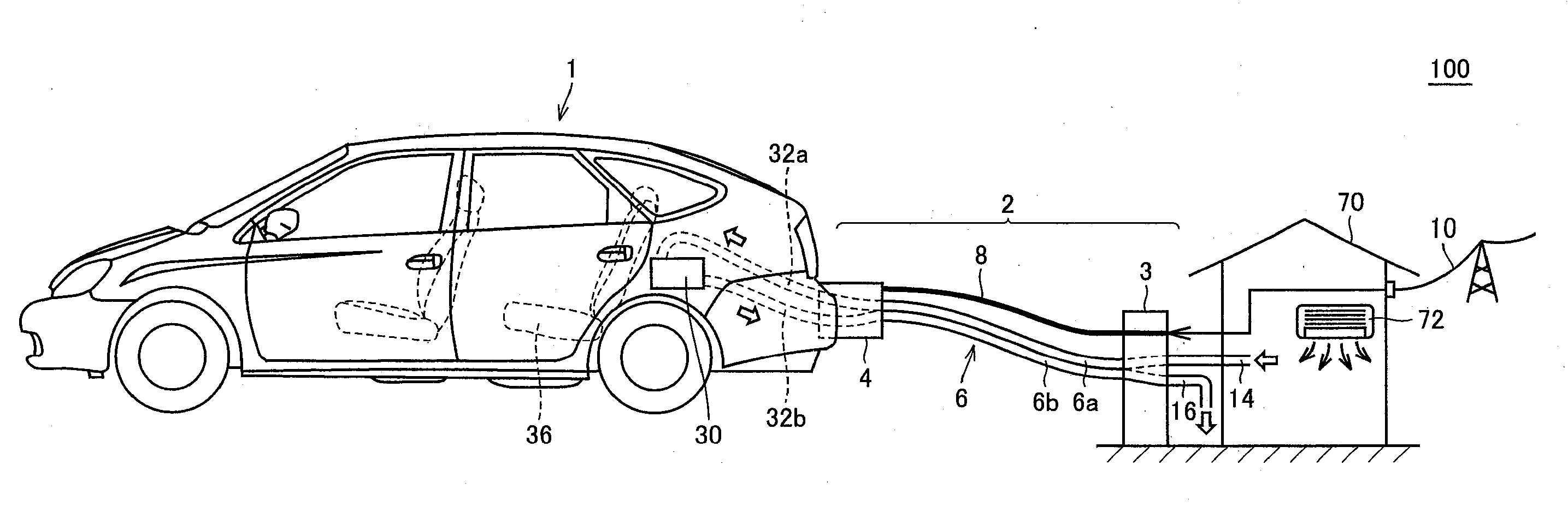
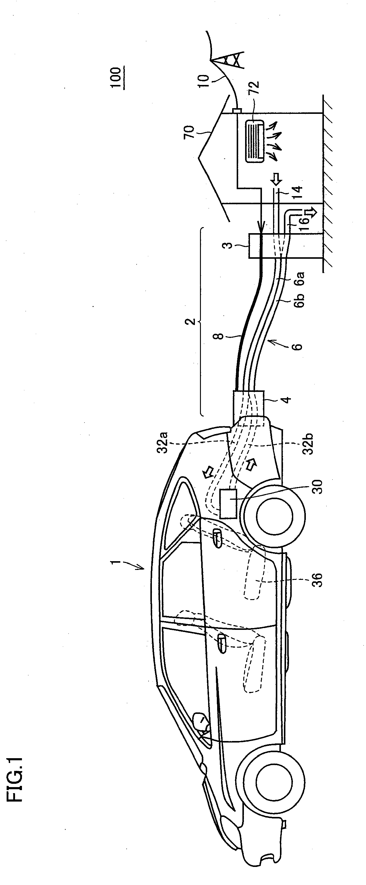
[0039]Referring to FIG. 1, a vehicle charging system 100 according to a first embodiment of the present invention includes an electric vehicle 1 and a vehicle charging apparatus 2.

[0040]Electric vehicle 1 is a hybrid vehicle as an example and has a power supply unit 30 mounted thereon. Power supply unit 30 is mainly for supplying electric power to a motor (not shown) that generates driving force of electric vehicle 1, and is configured to include a power storage device configured to be rechargeable. The power storage device is not limited to a secondary battery, but may be a fuel cell, a capacitor or the like. In a case where the power storage device is a secondary battery, the power storage device may be any of a lead-acid battery, a lithium-ion battery and a nickel-hydride battery, or may be a different type of battery from those batteries. It is noted that electric vehicle 1 may be an electrical vehicle, a fuel cell vehicle or the like as long as electric vehicle 1 has power supp...

second embodiment

[0092]Although the manner in which a part of the battery is configured as the heat capacity element is illustrated in the first embodiment of the present invention described above, any other heat capacity element may be used. In a second embodiment of the present invention, a configuration where a cooling path such as the PCU is used as the heat capacity element is illustrated.

[0093]The overall configuration of a vehicle charging system in the present embodiment is similar to that of vehicle charging system 100 according to the first embodiment of the present invention shown in FIG. 1, and the detailed description thereof will not be repeated. In the present embodiment, it is not necessarily required that the outside air-conditioned air be supplied from outside the vehicle. In other words, a configuration where only the external power supply is used as the external energy for storage of thermal energy in the heat capacity element is described in the present embodiment.

[0094]Referrin...


PUM


Abstract

When a current flows through a battery, a resistance loss proportional to the square of the current is produced by an internal resistance component of the current. In a case where the temperature of a heat capacity element is raised, a charging current is controlled such that prescribed thermal energy is provided to the heat capacity element by this resistance loss. Air is induced into a power supply unit through a vehicle compartment air exhaust duct. Then, the thermal energy stored in the heat capacity element is transferred to the air induced into the power supply unit. The air to which the thermal energy has been provided from the heat capacity element is blown out toward a vehicle compartment space by a fan.

Description

TECHNICAL FIELD [0001]The present invention relates to a technique for charging a power storage device configured to be rechargeable by an external power supply in an electric vehicle having the power storage device mounted thereon. In particular, the present invention relates to a technique for storing thermal energy in a vehicle, in addition to charge electric power.BACKGROUND ART [0002]So-called electric vehicles such as electrical vehicles, hybrid vehicles or fuel cell vehicles are equipped with a power storage device made up of a secondary battery, a capacitor or the like, and generate driving force from electric power stored in the power storage device through a motor.[0003]A configuration has been proposed in which the power storage device mounted on these electric vehicles is charged by an external power supply such as a system power supply or a solar cell. As for a hybrid vehicle, in particular, if the cost of charging by an external power supply is lower than that of elect...

Claims


Application Information

Patent Timeline
IPC IPC(8): B60R16/02
CPCB60H1/00257H05K7/20927B60H1/00428B60H2001/003B60K6/365B60K6/445B60L1/06B60L11/123B60L11/14B60L11/1812B60L11/1814B60L11/1816B60L11/1824B60L11/1862B60L11/1872B60L11/1874B60L15/007B60L2220/54B60L2240/34B60W10/26B60W10/30B60W20/00B60W2510/244Y02T10/6217Y02T10/6239Y02T10/6269Y02T10/641Y02T10/7005Y02T10/7044Y02T10/705Y02T10/7077Y02T90/121Y02T90/127Y02T90/14B60L11/1887Y02T90/34B60H1/00278B60L50/16B60L50/61B60L53/18B60L53/22B60L53/24B60L53/30B60L53/302B60L58/15B60L58/25B60L58/26B60L58/40Y02T10/62Y02T10/64Y02T10/70Y02T10/7072Y02T10/88Y02T90/12B60L53/14Y02T90/40
Inventor TAGUCHI, TOMONARI
Owner TOYOTA JIDOSHA KK
Why Eureka
Try Eureka