Fluidic circuit with bump features for improving uniform distribution of fluidic sprays

a technology of fluid spray and circuit, which is applied in the direction of metal-working equipment, printing, writing implements, etc., can solve the problem that two separate bumps may not fit under a narrower fan, and achieve the effect of breaking the performance envelope of a given s

Inactive Publication Date: 2010-04-15
ALLEN KERRIE +2
View PDF1 Cites 27 Cited by
  • Summary
  • Abstract
  • Description
  • Claims
  • Application Information

AI Technical Summary

Benefits of technology

[0009]Accordingly, it is an object of the present invention to overcome the above mentioned difficulties by providing a convenient, flexible, inexpensive and unobtrusive flui

Problems solved by technology

However, two separate bumps may not fit under a narrow

Method used


Image

  • Fluidic circuit with bump features for improving uniform distribution of fluidic sprays
  • Fluidic circuit with bump features for improving uniform distribution of fluidic sprays
  • Fluidic circuit with bump features for improving uniform distribution of fluidic sprays

Examples


Embodiment Construction

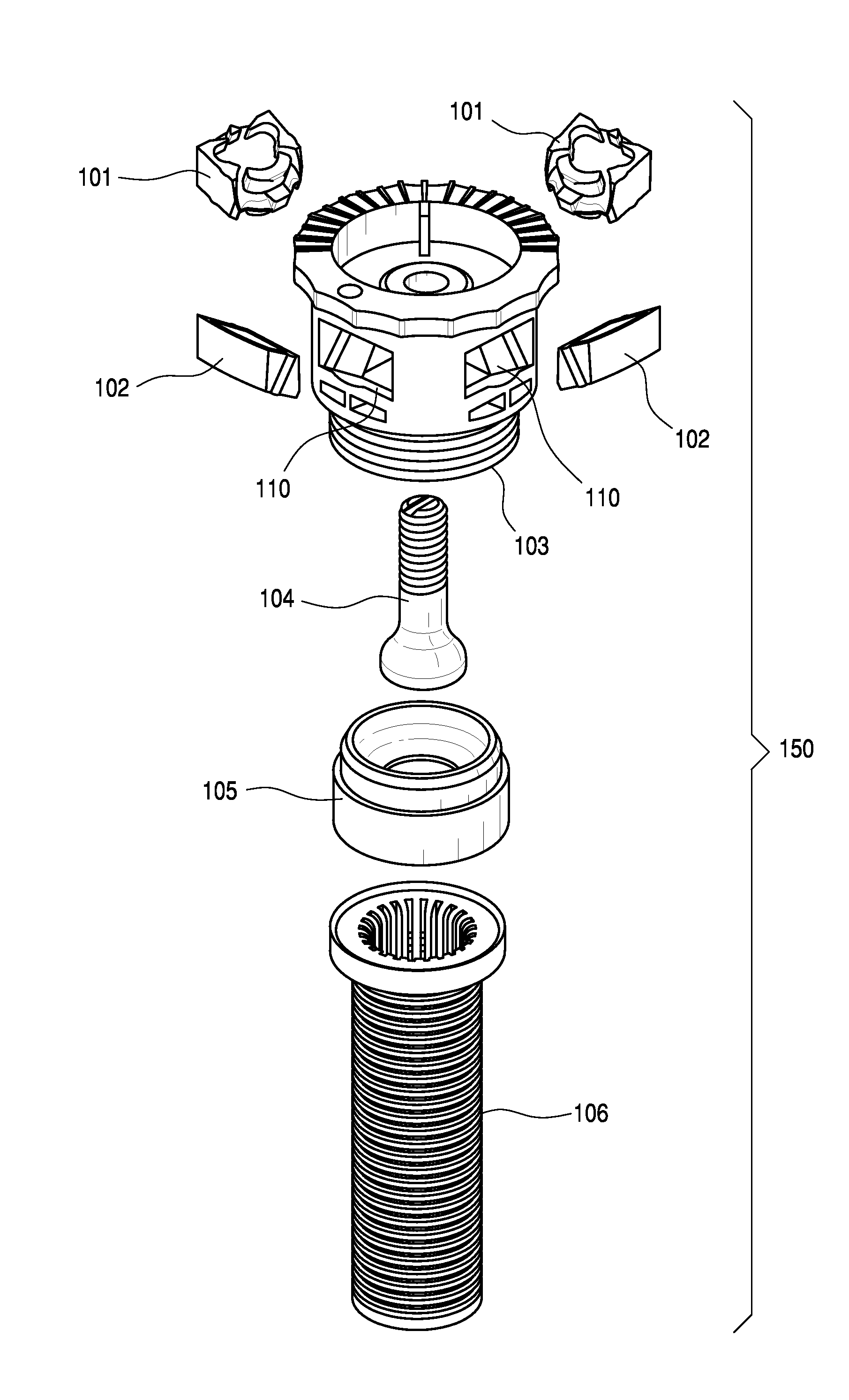
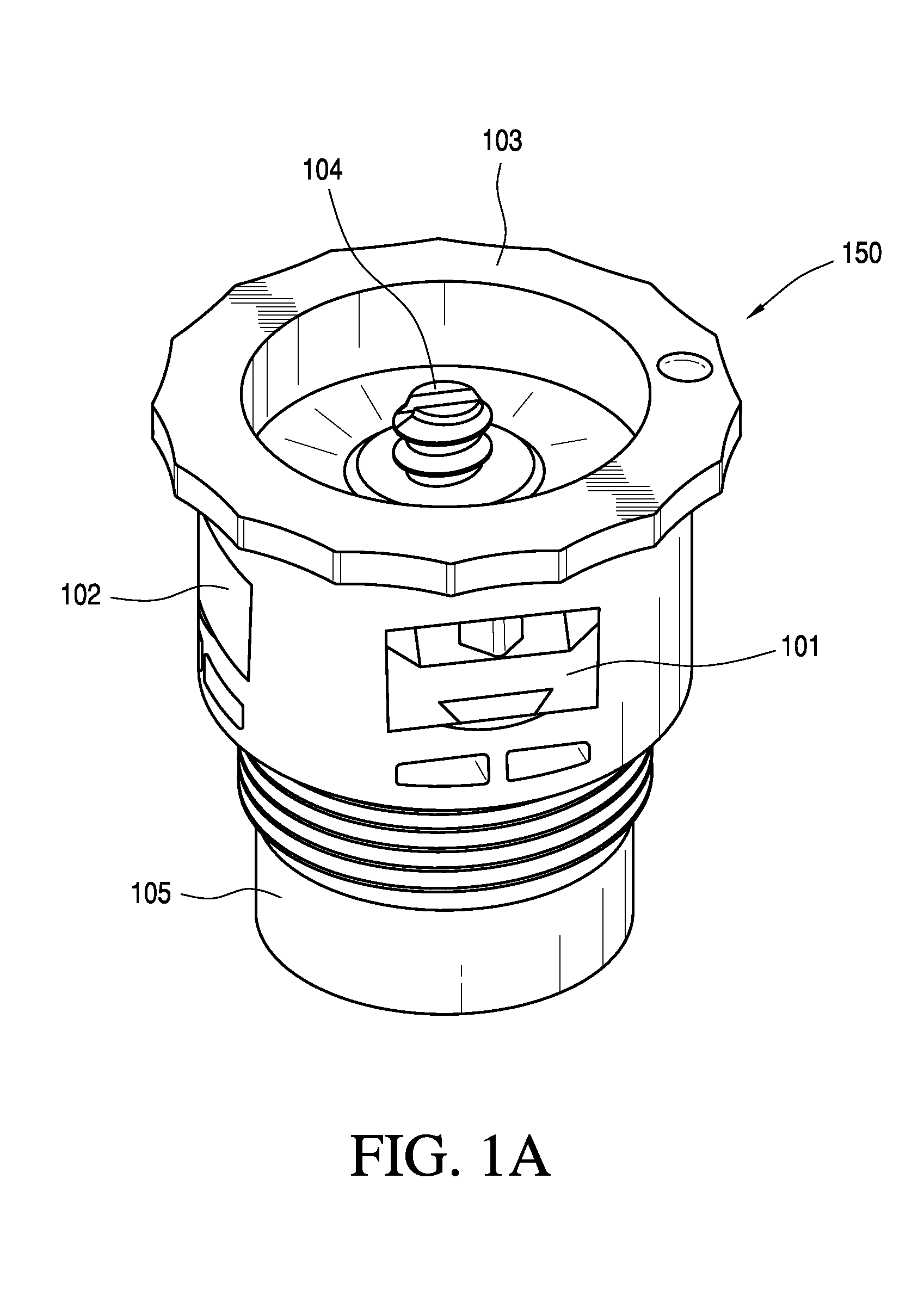
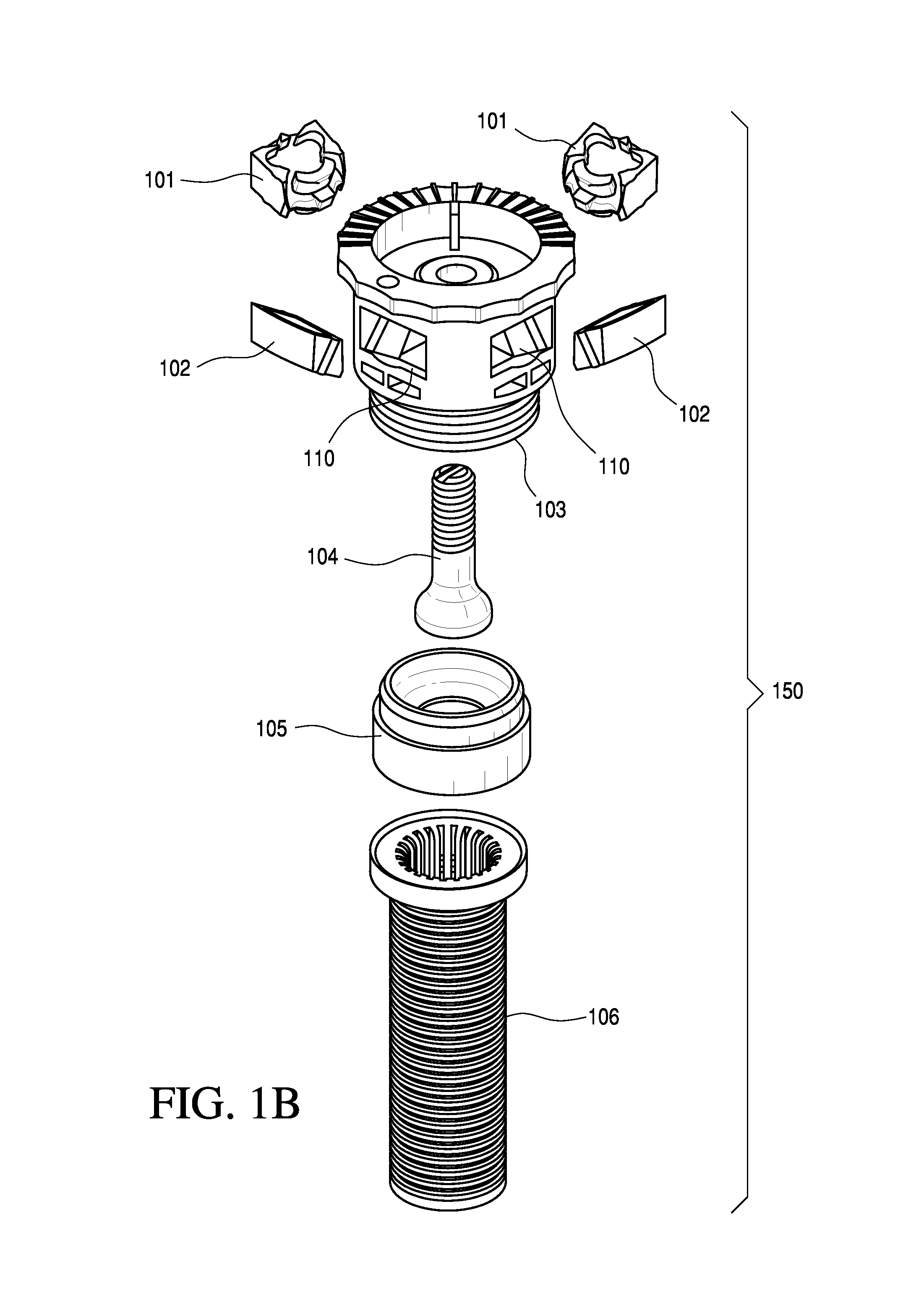
[0030]Referring now to FIGS. 1A-13, fluidic circuits are often configured for use in housings which define a channel, port or slot that receives and provides boundaries for the fluid paths defined in the fluidic circuit. For an illustrative example of how a fluidic oscillator or fluidic circuit might be employed, as shown in FIGS. 1A-5, a sprinkler or nozzle assembly 150 is configured with a substantially cylindrical housing 103 with a hollow interior. Housing 103 defines a substantially tubular fluid-impermeable structure and the housing sidewall includes an array of four upwardly angled ports or slots 110, each defining a substantially rectangular passage or aperture with smooth interior slot wall surfaces. The interior sidewall surfaces are preferably dimensioned for cost effective fabrication using molding methods and preferably include sidewall grooves positioned and dimensioned to form a “snap fit” with ridges or tabs in mating fluidic circuit inserts (e.g., 101) or blanks (e....


PUM

PropertyMeasurementUnit
Fractionaaaaaaaaaa
Fractionaaaaaaaaaa
Diameteraaaaaaaaaa

Abstract

A fluidic circuit or oscillator is provided with one or more small raised bumps or protrusions near the outlet or exhaust of a fluidic circuit to alter the spray pattern by re-distributing heavy areas of flow, resulting in a more uniform spray. The fluidic oscillator enclosure operates on a pressurized liquid flowing through the oscillator to generate a liquid jet that flows from said oscillator and into a surrounding environment to form an oscillating spray of liquid droplets, where the oscillator generates a stream of liquid droplets. The outlet or throat structure includes at least one bump or protuberance configured to project into the oscillating spray.

Description

PRIORITY CLAIMS AND REFERENCE TO RELATED APPLICATIONS[0001]This application claims priority to related and commonly owned U.S. provisional patent application No. 61 / 136,745, filed Sep. 30, 2009, the entire disclosure of which is incorporated herein by reference. This application is commonly owned with related U.S. patent application Nos. 61 / 012,200, 61 / 136,744 and 12 / 314,242 the entire disclosures of which are also incorporated herein by reference.BACKGROUND OF THE INVENTION[0002]1. Field of the Invention[0003]The present invention relates to fluidic circuits and nozzle assemblies configured with fluidic oscillators and other fluidic circuits.[0004]2. Discussion of the Prior Art[0005]A fluidic nozzle creates a stream of fluid that oscillates within an included angle, known as the fan angle. The distribution of the fluid within this fan will vary depending on the type of fluidic circuit used. For example, in a mushroom circuit, the oscillating stream will tend to dwell briefly at the...

Claims


Application Information

Patent Timeline
IPC IPC(8): B05B1/08B23P17/00
CPCB05B1/08B05B1/202Y10T29/49401B05B15/10B05B1/262B05B15/74
Inventor ALLEN, KERRIERUSSELL, GREGORYGOPALAN, SHRIDHAR
Owner ALLEN KERRIE
Why Eureka
Try Eureka