Fluid Machine, Rankine Circuit, and System for Utilizing Waste Heat from Vehicle

a technology of rankine circuit and waste heat, which is applied in the direction of machines/engines, rotary piston liquid engines, electric generator control, etc., can solve the problems of reducing the power generation efficiency of the generator, the dc motor is larger than the ac motor, etc., and achieves improved fuel consumption of the vehicle, simple configuration, and easy installation in the vehicle

Inactive Publication Date: 2010-04-15
SANDEN CORP
View PDF11 Cites 29 Cited by
  • Summary
  • Abstract
  • Description
  • Claims
  • Application Information

AI Technical Summary

Benefits of technology

[0057]The system for utilizing waste heat from a vehicle according to the invention has a simple configuration because a single fluid machine functions as a pump, an expander, and a generator. A configuration for connecting the internal combustion engine and the power transmission device of the fluid machine to each other is also simple. Consequently, the system for utilizing waste heat is easy to install in a vehicle.
[0058]According to the system for utilizing waste heat, the waste heat from the internal combustion engine is converted into electric power, so that fuel consumption of the vehicle is improved. Moreover, since the internal combustion engine and the power transmission unit of the fluid machine are connected to each other, it is possible to convert a kinetic energy into electric power when the vehicle is braked or decelerated. According to the system for utilizing waste heat, therefore, the fuel consumption of the vehicle is further improved.

Problems solved by technology

In general, a DC motor has larger weight than an AC motor, and has lower power generation efficiency when being used as a generator.

Method used


Image

  • Fluid Machine, Rankine Circuit, and System for Utilizing Waste Heat from Vehicle
  • Fluid Machine, Rankine Circuit, and System for Utilizing Waste Heat from Vehicle
  • Fluid Machine, Rankine Circuit, and System for Utilizing Waste Heat from Vehicle

Examples


first embodiment

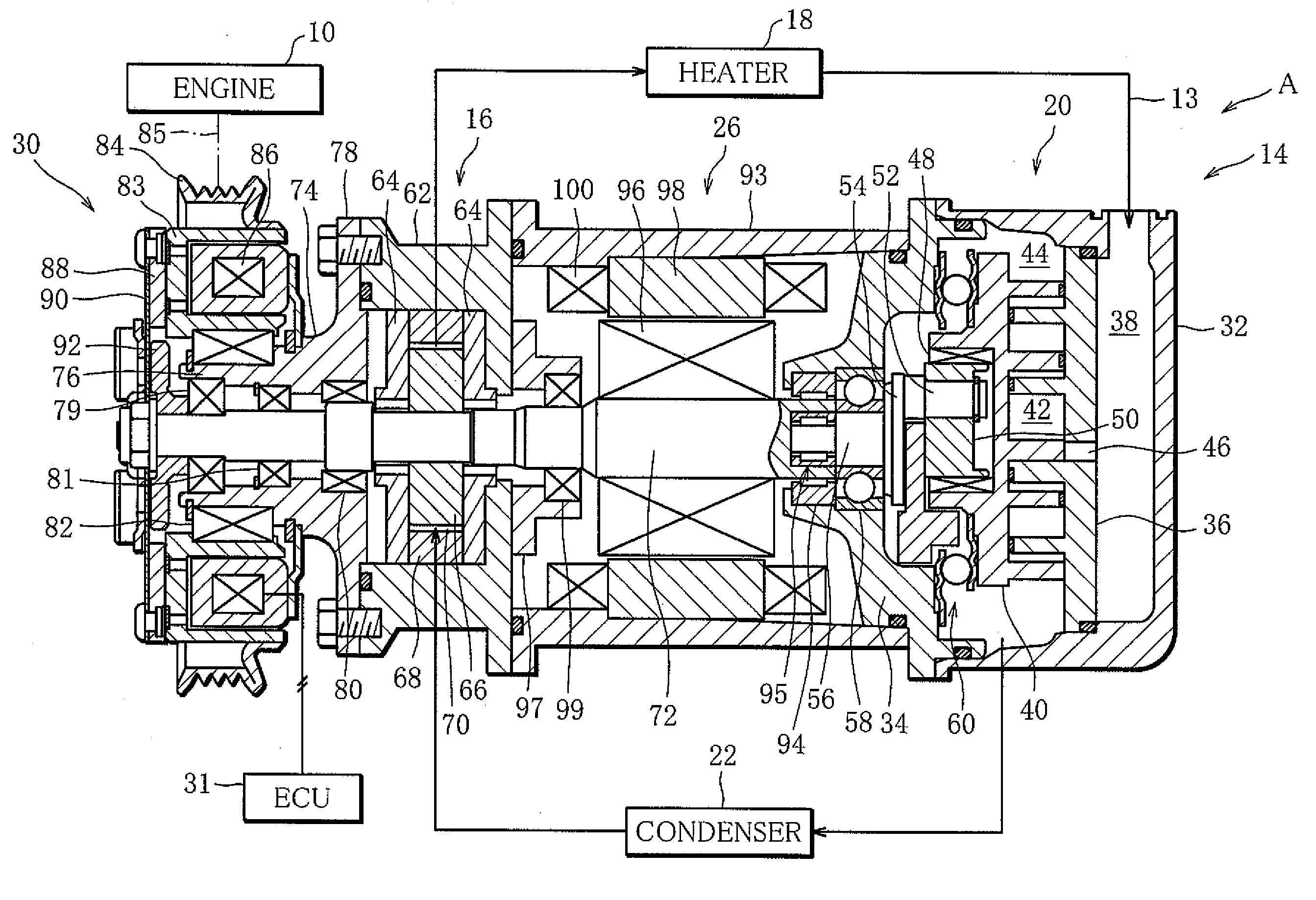
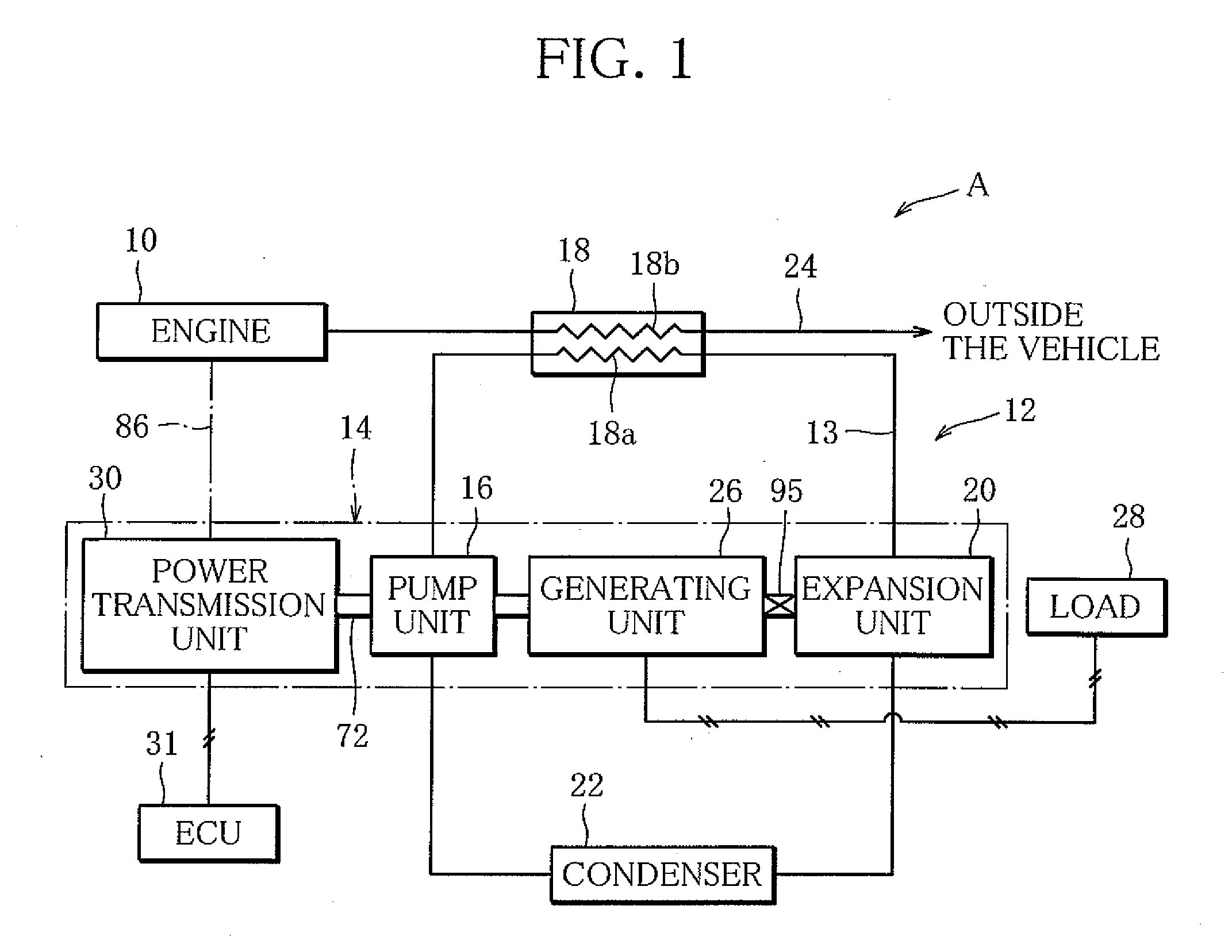
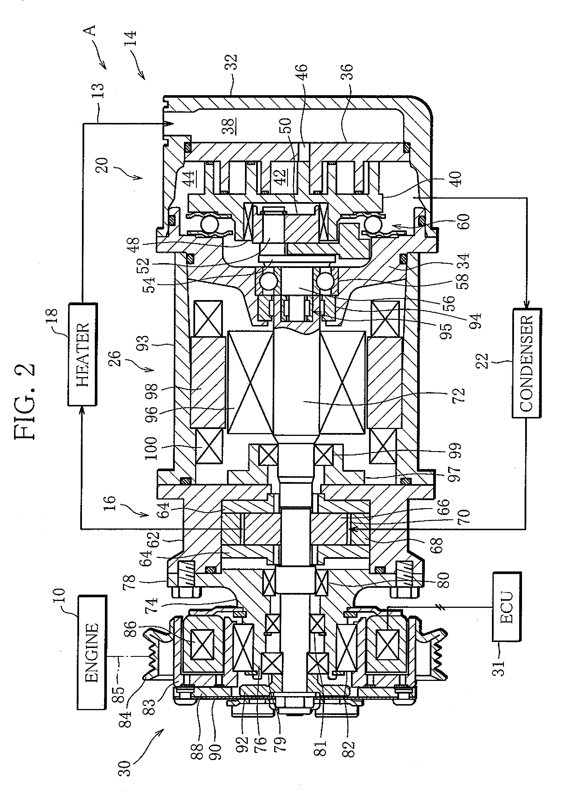
[0069]FIG. 1 shows a system A for utilizing waste heat from a vehicle according to a The system A for utilizing waste heat, for example, retrieves the heat of exhaust gas discharged from a vehicle engine (internal combustion engine) 10. The system A for utilizing waste heat has a Rankine circuit 12. The Rankine circuit 12 includes a circulation path 13 through which a working fluid (heat medium) circulates. The circulation path 13 is constructed, for example, of a duct or a pipe.

[0070]A pump unit 16 of a fluid machine 14 is interposed in the circulation path 13 in order to flow the working fluid. Furthermore, a heater 18, an expansion unit 20 of the fluid machine 14, and the condenser 22 are also interposed in the circulation path 13 on the downstream side of the pump unit 16 as seen in a direction that the working fluid flows. The pump unit 16 draws in the working fluid on the condenser 22 side. The pump unit 16 then pressurizes the working fluid that has been drawn in, and discha...

fourth embodiment

[0129]FIG. 5 is a view showing a schematic configuration of a system D for utilizing waste heat from a vehicle according to a Components identical to those of the systems A to C for utilizing waste heat will be provided with the same reference marks, and the explanation thereof will be omitted.

[0130]In a fluid machine 120 applied to the system D for utilizing waste heat, the power transmission unit 30, the internal gear 66 of the pump unit 16, the rotor 96 of the generating unit 30, and the shaft 56 of the expansion unit 20 are integrally connected to a single drive shaft 122.

[0131]The system D for utilizing waste heat further includes an external return path 124 disposed in the circulation path 13 in parallel with the expansion unit 20, and an electromagnetic valve 126 functioning as a return-path on-off valve, which is interposed in the external return path 124. The electromagnetic valve 126 is capable of opening / closing the external return path 124 in response to signals from th...

fifth embodiment

[0136]FIG. 6 shows a schematic configuration of a system E for utilizing waste heat from a vehicle according to a Components identical to those of the systems A to D for utilizing waste heat will be provided with the same reference marks, and the explanation thereof will be omitted.

[0137]The system E for utilizing waste heat has a non-return valve 128 functioning as a return-path on-off valve. When pressure on the immediate downstream side of the expansion unit 20 becomes lower than pressure on the immediate upstream of the expansion unit 20, the non-return valve 128 allows the working fluid to flow from downstream to upstream. The non-return valve 128 automatically suppresses a pressure drop in the section of the circulation path 13, which extends between the circulation-path on-off valve 104 and the expansion unit 20. Similarly to the electromagnetic valve 126, the non-return valve 128 reduces the load applied from the expansion unit 20 to the drive shaft 122, when accumulating t...


PUM


Abstract

A system for utilizing waste heat from a vehicle has a Rankine circuit, and the Rankine circuit includes a fluid machine. A generating unit of the fluid machine has a third rotating body that is disposed coaxially with a first rotating body of a pump unit and a second rotating body of an expansion unit. The fluid machine has a drive shaft that is integrally connected at least to the first rotating body, among the first, second and third rotating bodies, and a power transmission unit that is connected to the drive shaft and transmits external power to the drive shaft.

Description

TECHNICAL FIELD[0001]The present invention relates to a fluid machine, a Rankine circuit, and a system for utilizing waste heat from a vehicle.BACKGROUND ART[0002]A Rankine circuit constructing a system for utilizing waste heat of an inner combustion engine, such as a vehicle engine, has a circulation path through which a working fluid (heat medium) circulates. A pump, an evaporator (heat exchanger), an expansion machine, and a condenser are interposed in the circulation path in the order named.[0003]The pump is driven, for example, by an electric motor to circulate the working fluid. The working fluid receives waste heat when passing through the evaporator, and is expanded in the expansion machine. In this process, the thermal energy of the working fluid is converted into torque and outputted outside. The thermal energy is thus used, for example, to rotate a fan for air-cooling the condenser.[0004]As a compact and inexpensive fluid machine that is suitable for the Rankine circuit, ...

Claims


Application Information

Patent Timeline
Patent Type & Authority Applications(United States)
IPC IPC(8): F02B63/04F01K27/00H02P9/14
CPCF01C11/006F02G5/00F02G5/02Y02T10/166F02G2260/00F04C18/0215F25B11/02F02G5/04Y02T10/12
Inventor WADA, HIROFUMI
Owner SANDEN CORP
Why Eureka
Try Eureka