
Hydrogen separation membrane and permselective membrane reactor

a technology of hydrogen separation membrane and permselective membrane, which is applied in the direction of membranes, separation processes, physical/chemical process catalysts, etc., can solve the problems of poor durability of separation membrane, difficult to achieve excellent hydrogen permeability and durability at the same time, and achieve excellent hydrogen permeability and durability. , the effect of improving durability

Inactive Publication Date: 2010-04-15
NGK INSULATORS LTD
View PDF21 Cites 13 Cited by
  • Summary
  • Abstract
  • Description
  • Claims
  • Application Information

AI Technical Summary

Benefits of technology

[0014]When the thickness of the hydrogen separation membrane is increased to suppress formation of defects, the hydrogen permeability of the separation membrane decreases.
[0016]The present invention was conceived in view of the above problems. An object of the present invention is to provide a hydrogen separation membrane that is provided with excellent durability in addition to excellent hydrogen permeability by suppressing formation or growth of defects, and a selectively permeable membrane reactor using the hydrogen separation membrane.
[0020]The hydrogen separation membrane of the present invention exhibits excellent hydrogen permeability and durability. Specifically, since the element distribution required to improve durability can be implemented by adding the two metals having a specific solid solubility to palladium, defects of the hydrogen separation membrane can be prevented. Therefore, the durability of the hydrogen separation membrane can be improved.
[0021]Since the hydrogen separation membrane according to the present invention exhibits excellent durability, the thickness of the hydrogen separation membrane can be reduced so that the amount of palladium used for the hydrogen separation membrane can be reduced. This is advantageous from the viewpoint of cost. Moreover, since the alloy is formed by adding the two metals other than palladium to palladium, the content of palladium in the alloy can be reduced.
[0022]Since the selectively permeable membrane reactor according to the present invention utilizes the hydrogen separation membrane according to the present invention, the selectively permeable membrane reactor exhibits excellent hydrogen permeability and durability. Moreover, since the amount of relatively expensive palladium used for the hydrogen separation membrane can be reduced, the reactor can be produced at low cost.

Problems solved by technology

A hydrogen separation membrane formed using palladium or a palladium alloy that contains palladium and another metal may suffer from formation or growth of defects during use at a high temperature (i.e., the separation membrane exhibits poor durability).
It has been very difficult to achieve excellent hydrogen permeability and durability at the same time.

Method used


Image

  • Hydrogen separation membrane and permselective membrane reactor
  • Hydrogen separation membrane and permselective membrane reactor
  • Hydrogen separation membrane and permselective membrane reactor

Examples


example 1

[0086]An α-alumina tube having a cylindrical shape (outer diameter: 10 mm, length: 100 mm, average surface pore size: 0.1 μm) was used as a substrate. Palladium, copper, and silver were sequentially deposited on the surface of the cylindrical substrate using a plating method to form a laminate. Palladium, copper, and silver were deposited so that the rate of silver was 25 parts by mass, and the rate of copper was 9 parts by mass with respect to 100 parts by mass of palladium. The resulting laminate was alloyed by heat treating at 700° C. for one hour in argon gas to obtain a hydrogen separation membrane formed of the palladium alloy. The thickness of the hydrogen separation membrane was 2 μm.

[0087]After sealing the ends of the cylindrical substrate on which the hydrogen separation membrane was disposed, the substrate was placed in a pressure-resistant container to obtain a hydrogen separator having the hydrogen separation membrane. The hydrogen separation membrane used for the hydro...

examples 2 and 3

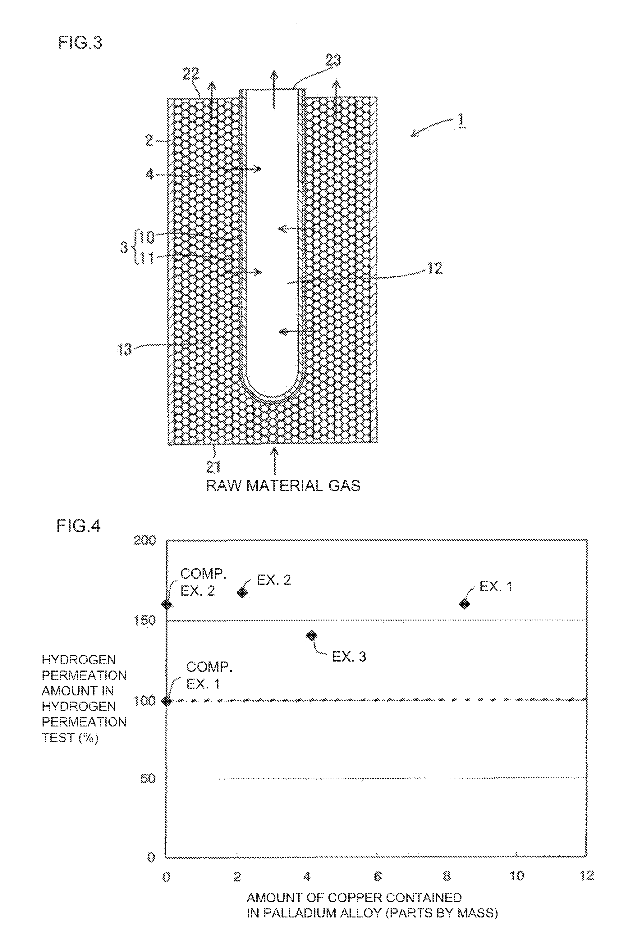
[0090]A hydrogen separation membrane was formed in the same manner as in Example 1, except that the amount of copper forming the palladium alloy was changed as shown in Table 1. A hydrogen separator was produced using the resulting hydrogen separation membrane. The measurement results of the hydrogen permeation test are shown in Table 1.

examples 4 to 10

[0095]A hydrogen separation membrane was formed in the same manner as in Example 1, except that the ratio of the elements forming the palladium alloy was changed as shown in Table 3. A hydrogen separator was produced using the resulting hydrogen separation membrane. The measurement results of the hydrogen permeation test of Examples 2 and 4 to 10 are shown in Table 3.

TABLE 3Results ofhydrogenComposition of palladium alloypermeation(parts by mass)test (%)Example 2Palladium (100)silver (25)Copper (2)167Example 4Palladium (100)silver (25)Nickel (2)145Example 5Palladium (100)silver (25)Cobalt (2)140Example 6Palladium (100)silver (25)Iridium (2)150Example 7Palladium (100)silver (25)Rhodium (2)168Example 8Palladium (100)Gold (5)Cobalt (2)85Example 9Palladium (100)Gold (5)Iridium (2)96Example 10Palladium (100)Gold (5)Rhodium (2)95

(Results)

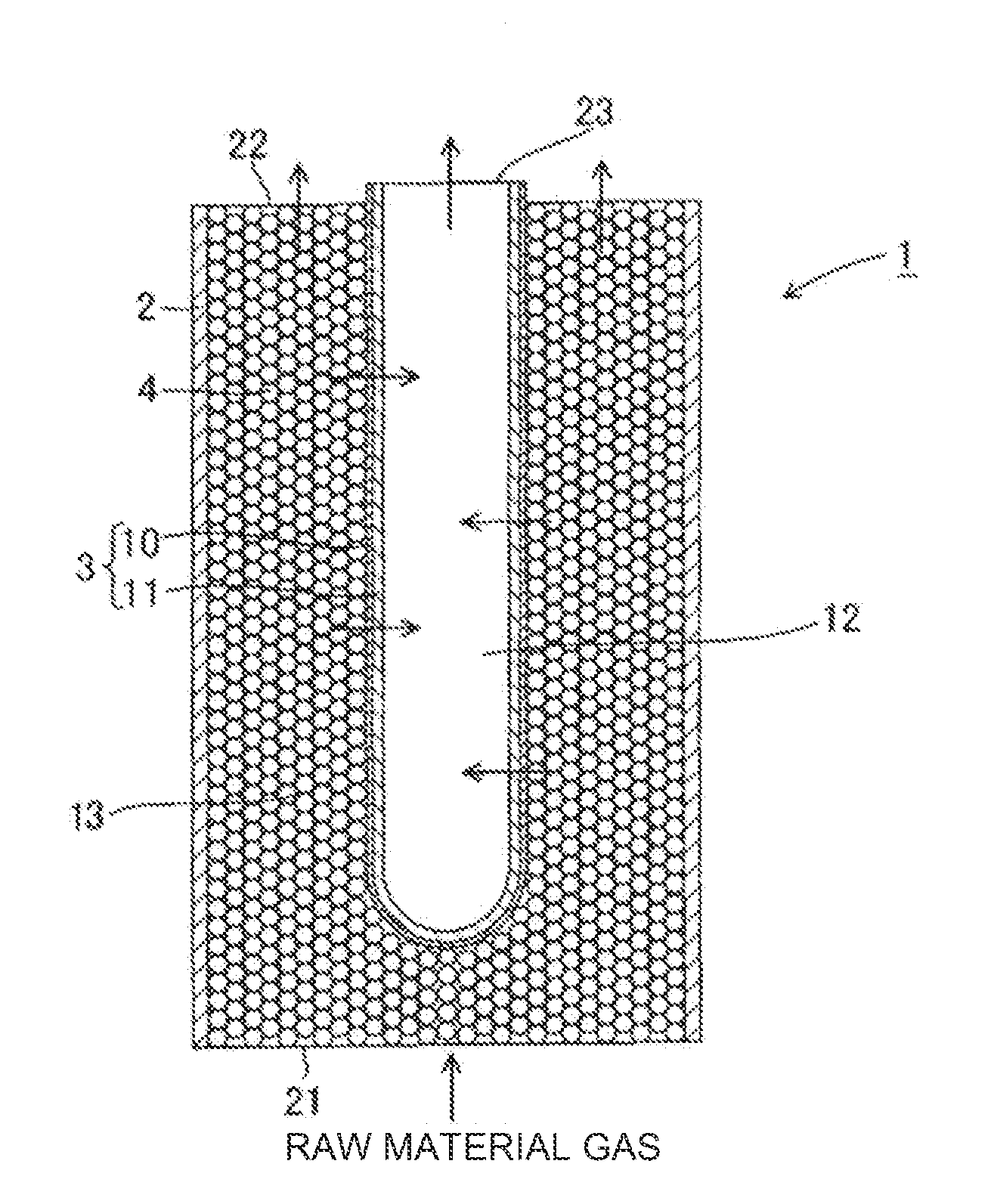
[0096]As shown in Table 1 and the graph of FIG. 4, the hydrogen separation membranes used for the hydrogen separators of Examples 1 to 3 exhibited excell...


PUM

PropertyMeasurementUnit
temperatureaaaaaaaaaa
thicknessaaaaaaaaaa
thicknessaaaaaaaaaa

Abstract

A hydrogen separation membrane comprising a palladium alloy that includes at least palladium, an added metal A, and an added metal B, the added metal A and the added metal B being two different metals other than palladium, each of the added metal A and the added metal B forming a complete solid solution with palladium, and the added metal A and the added metal B having a triple point in an equilibrium diagram and not forming an intermetallic compound. The hydrogen separation membrane exhibits excellent hydrogen permeability and durability.

Description

TECHNICAL FIELD[0001]The present invention relates to a hydrogen separation membrane and a selectively permeable membrane reactor. More particularly, the present invention relates to a hydrogen separation membrane that exhibits excellent hydrogen permeability and durability, and a selectively permeable membrane reactor using the hydrogen separation membrane.BACKGROUND ART[0002]A large amount of hydrogen gas has been used as a petrochemical basic material gas. Hydrogen gas has also attracted attention as a clean energy source. Hydrogen gas used for such purposes is produced from hydrocarbons (e.g., methane, propane, butane, or kerosene) or oxygenated hydrocarbons (e.g., methanol) as a main raw material gas by utilizing a reforming reaction, a partial oxidation reaction, an self-heating reaction, a decomposition reaction, or the like. Hydrogen gas is also produced by subjecting by-product carbon monoxide and water to a shift reaction. Hydrogen thus produced can be separated and collec...

Claims


Application Information

Patent Timeline
Patent Type & Authority Applications(United States)
IPC IPC(8): B01D71/02B01D69/12C01B3/38C01B3/56
CPCB01D53/228C22C5/04B01D71/022B01D2256/16B01D2323/08B01D2325/28B01J8/0257B01J19/2485B01J2208/00088B01J2219/00069C01B3/384C01B3/505C01B2203/0233C01B2203/04C01B2203/041C01B2203/047C01B2203/0475C01B2203/066C01B2203/0805C01B2203/1011C01B2203/1023C01B2203/1047C01B2203/1052C01B2203/1064C01B2203/107C01B2203/1076C01B2203/1082C01B2203/1211C01B2203/1217C01B2203/1223C01B2203/1229C01B2203/1241C01B2203/1247B01D69/02Y02P20/52
Inventor NODA, KENICHI
Owner NGK INSULATORS LTD
Learn More