Variable valve timing apparatus

a timing apparatus and variable valve technology, applied in the direction of valve arrangement, yielding coupling, coupling, etc., can solve the problems of inability to change the generating characteristics and input characteristics of the braking torque, the inability to maintain various characteristics, and the leakage of magneto-rheological fluid

Active Publication Date: 2010-04-22
DENSO CORP
View PDF5 Cites 19 Cited by
  • Summary
  • Abstract
  • Description
  • Claims
  • Application Information

AI Technical Summary

Benefits of technology

[0008]It is an object of the present invention to provide an improved variable valve timing apparatus.

Problems solved by technology

One technical problem of this kind of variable valve timing apparatus is that the magneto-rheological fluid which causes instability of various characteristics.
One technical problem of this kind of variable valve timing apparatus is a leak of the magneto-rheological fluid.
A leak may change generating characteristics and input characteristics of the braking torque.
In addition, a leak may affect adjusting characteristics of the engine phases and generates undesirable change on the characteristics.
One technical problem of this kind of variable valve timing apparatus is a pressure change in a fluid chamber where the magneto-rheological fluid is kept.
In addition, the pressure change is not stable since the pressure change is generated according to an environmental temperature or a heat generation by a braking action.

Method used


Image

  • Variable valve timing apparatus
  • Variable valve timing apparatus
  • Variable valve timing apparatus

Examples


first embodiment

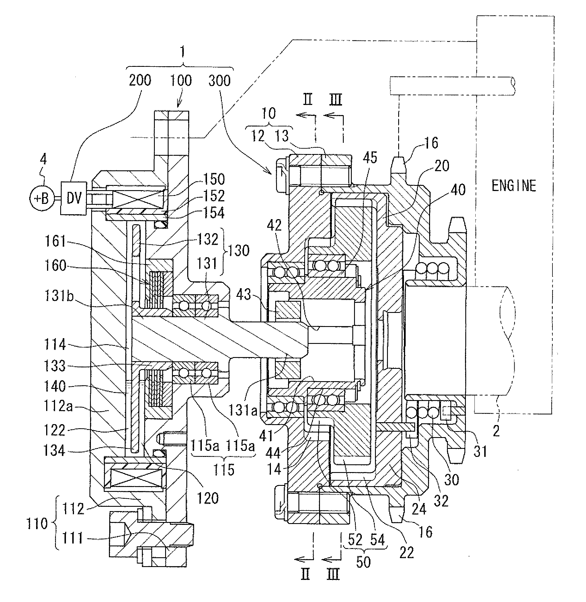
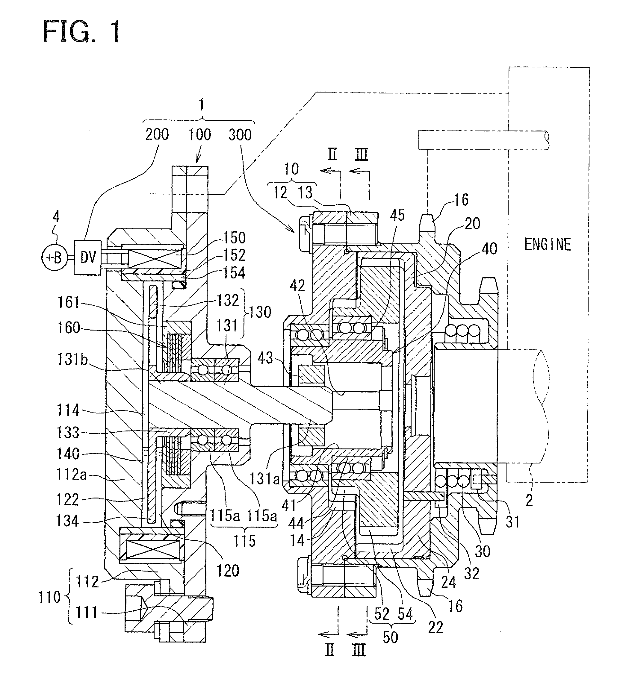
[0040]FIG. 1 shows the variable valve timing apparatus 1 according to the first embodiment of the present invention. The variable valve timing apparatus 1 adjusts valve timing of valve. The valve is driven in an open position and a close position by a camshaft 2. The camshaft 2 is rotated by torque transmission from the crankshaft of an internal combustion engine. The variable valve timing apparatus 1 is mounted on the engine on a vehicle. The variable valve timing apparatus 1 is installed in a torque transmission train which transmits engine torque to the camshaft 2 from the crankshaft. The camshaft 2 shown in FIG. 1 opens and closes at least one of intake valves among valves of the internal combustion engine. The variable valve timing apparatus 1 adjusts the valve timing of the intake valve. The variable valve timing apparatus 1 in the first embodiment has an actuator 100, a control circuit (DV) 200, and a phase adjusting mechanism 300. The control circuit 200 is a circuit supplyi...

second embodiment

[0056]As shown in FIG. 6, the second embodiment of the present invention is a modification of the first embodiment. The actuator 500 in the second embodiment is provided with a sealing device 560 and a nonmagnetic shield member 561. The components 560 and 561 are different from the first embodiment.

[0057]The nonmagnetic shield member 561 has a main part 561a and a cover part 561b. The main part 561a is substantially identical to the nonmagnetic shield member 161 of the first embodiment. The main part 561a has a cylindrical part and a bottom wall part on one end of the cylindrical part. The cover part 561b covers the other end of the cylindrical part. The cover part 561b is formed in an annular plate shape and is made of the same magnetic material as the main part 561a. The cover part 561b is placed on a radial outside to the boss part 133. The cover part 561b is disposed next to the bearing 115 on the inside of the case 110. The cover part 561b and the bottom wall portions 161a of t...

third embodiment

[0063]FIG. 8 shows an actuator 600 for the variable valve timing apparatus 1 according to the third embodiment. FIG. 8 is an enlarged sectional view showing a similar portion shown in FIGS. 4 and 6. FIG. 9 is a schematic diagram for explaining the actuator 600 in FIG. 8. As shown in FIG. 8, the embodiment is a modification of the second embodiment. The actuator 600 in the embodiment is provided with a sealing device 660, a rotor 630 and a case 110. The components 660, 630 and 110 are different from the second embodiment. The sealing device 660 has the magnet 162 which is the same as in the second embodiment, and the nonmagnetic shield member 561 which is substantially the same as the second embodiment. The sealing device 660 further has flux guides 664a and 664a which are different from the preceding embodiment. One flux guide 664a is arranged on one side of the magnet 162. The other one flux guide 664a is arranged on the other side of the magnet 162. In other word, the flux guides ...


PUM


Abstract

A variable valve timing apparatus has a case, a rotor, and a magneto-rheological fluid. The magneto-rheological fluid gives variable braking force to the rotor. The rotor is connected with a phase adjusting mechanism. The phase adjusting mechanism adjusts a phase of an internal combustion engine according to braking force. A sealing device is disposed between the case and the rotor. In one embodiment, the sealing device has a magnet and a plurality of flux guide members. In other embodiment, a diaphragm which acts as a damper mechanism for absorbing an internal pressure change is disposed on a fluid chamber in which the magneto-rheological fluid is kept.

Description

CROSS REFERENCE TO RELATED APPLICATION[0001]This application is based on Japanese Patent Applications No. 2008-272378 filed on Oct. 22; 2008, 2008-272379 filed on Oct. 22, 2008; 2009-112988 filed on May 7, 2009; and 2009-125739 filed on May 25, 2009, and the contents of which are incorporated herein by reference in its entirety.FIELD OF THE INVENTION[0002]The present invention relates to a variable valve timing apparatus for adjusting valve timing of an internal combustion engine.BACKGROUND OF THE INVENTION[0003]Conventionally, a variable valve timing apparatus which adjusts a relative angular phase between a crankshaft and a camshaft according to a braking torque generated by an actuator is known. The relative angular phase may be called as an engine phase indicating a valve operating timing. One of the variable valve timing apparatus is disclosed in JP 2008-51093A. The apparatus generates a braking torque by a fluidic actuator for adjusting the engine phase.[0004]In detail, the ap...

Claims


Application Information

Patent Timeline
Patent Type & Authority Applications(United States)
IPC IPC(8): F01L1/34
CPCF01L1/344F01L2001/3522F01L2001/34483F01L1/352
Inventor MORISHIMA, SHINGO
Owner DENSO CORP
Why Eureka
Try Eureka