Well liner segments for in situ petroleum upgrading and recovery, and method of in situ upgrading and recovery

Inactive Publication Date: 2010-04-22
ARCHON TECH LTD
View PDF14 Cites 19 Cited by
  • Summary
  • Abstract
  • Description
  • Claims
  • Application Information

AI Technical Summary

Benefits of technology

[0008]The present invention relates to horizontal well liner designs which allow increased time or extent of exposure in which produced oil is exposed to upgrader catalyst during in situ hydrocarbon prod

Problems solved by technology

While the bore hole may be drilled larger by reaming operations to leave more space between the liner and the reservoir, this is an additional expense.
Disadvantageously, however, with this prior art method, since the resulting vertical pat

Method used


Image

  • Well liner segments for in situ petroleum upgrading and recovery, and method of in situ  upgrading and recovery
  • Well liner segments for in situ petroleum upgrading and recovery, and method of in situ  upgrading and recovery
  • Well liner segments for in situ petroleum upgrading and recovery, and method of in situ  upgrading and recovery

Examples


first embodiment

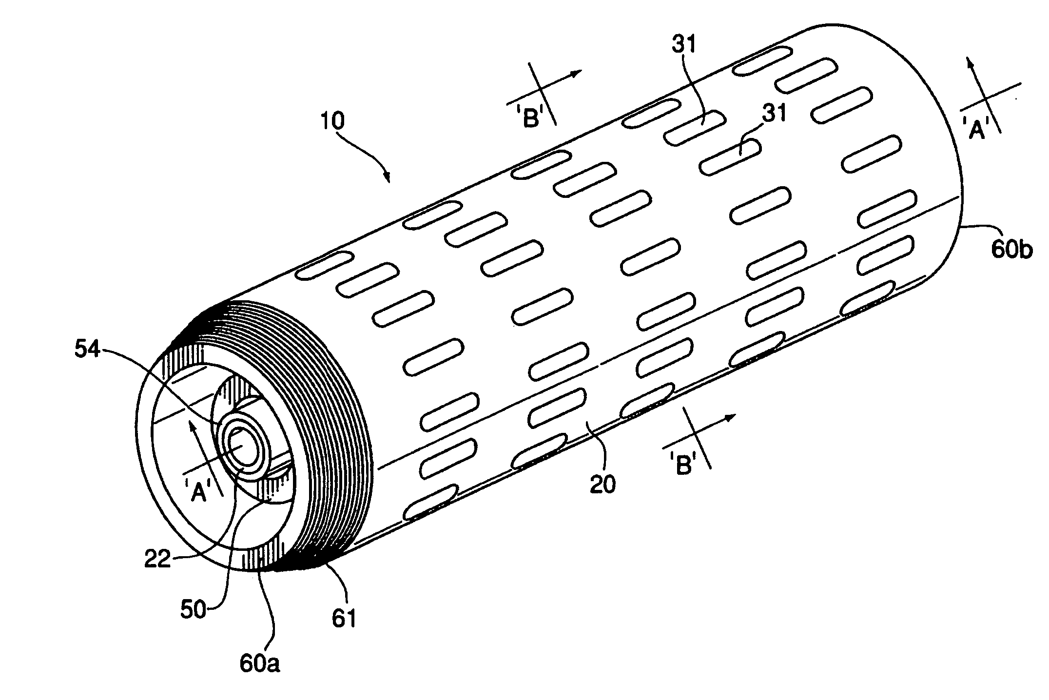
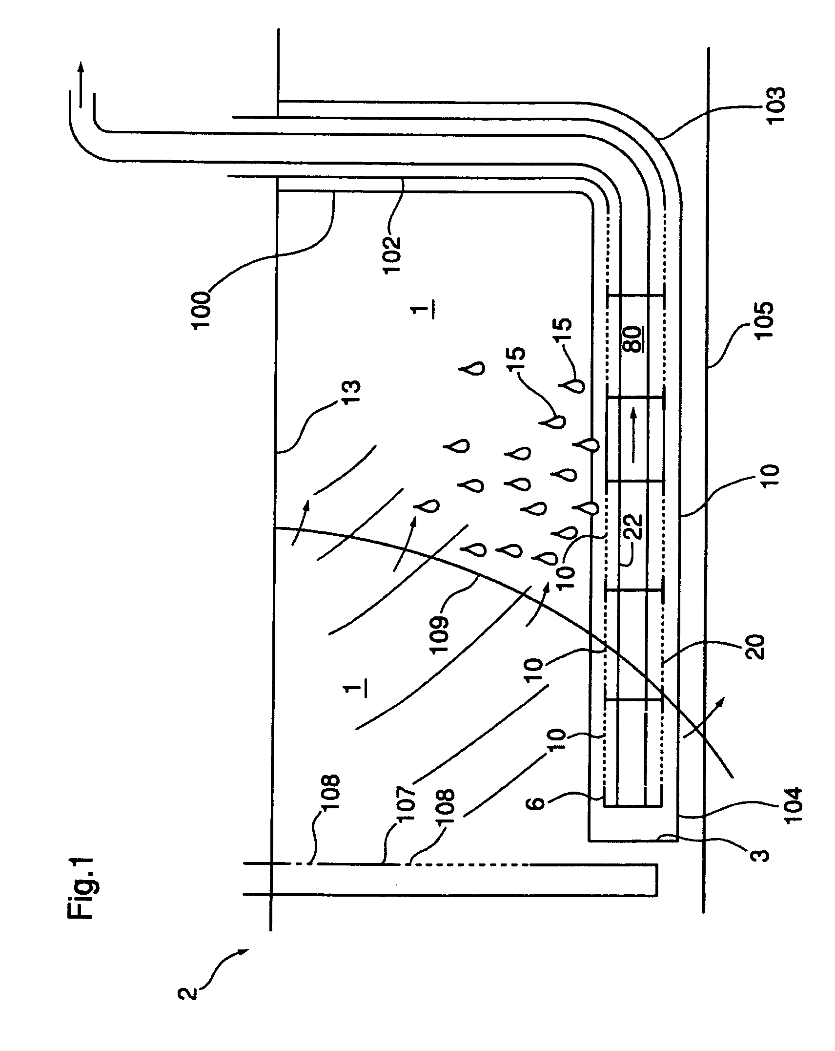
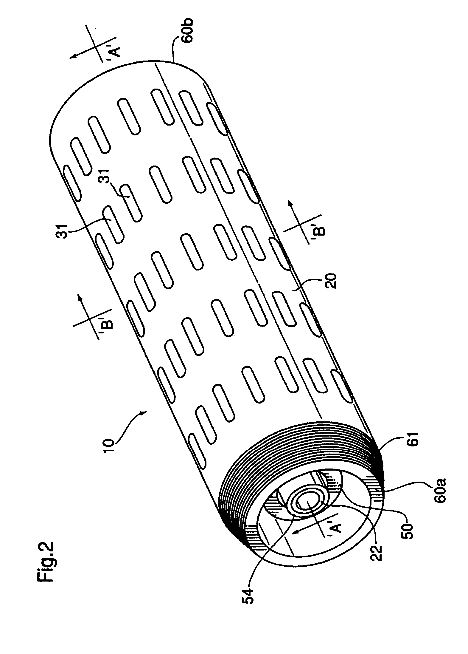
[0068]In a first embodiment and as shown in FIGS. 2 & 4a, apertures / slots 31 are evenly spaced about a periphery of outer member 22. Similarly, apertures / slots 41 in interior member 22 are likewise equally spaced about an entire periphery thereof. Apertures / slots 41 are typically larger in width than apertures 31, as there is no remaining need to attempt to “screen” sand from the viscous oil 15 entering interior member 22. Viscous oil 15 consequently flows directly radially inwardly through catalyst 40 in interstitial space 12 into interior area 80 in internal member 22, as seen in FIG. 4a.

[0069]Alternatively, as seen in FIG. 4b, apertures / slots 31 in outer member 20 may be situated only on an upper portion of outer member 20, and apertures / slot 41 in inner member 22 situated on a lower portion thereof. A vice versa arrangement is also contemplated. Under either of the two alternative configurations, viscous oil 15, as shown in FIG. 4b, will necessarily be required to travel a circ...

second embodiment

[0078]In a second embodiment, a first version of which is shown in FIG. 12, the sliding seal 52 comprises merely a single (outer) ring member 50 fixedly secured to said outer member 20, as shown in FIG. 12, to allow not only longitudinal expansion of said inner liner member 22 to said outer liner member 20, but also provide some clearance 55 to permit some radial growth due to thermal expansion in a radial direction. In a second version, shown in FIG. 13, the sliding seal 52 comprises merely a single (inner) ring member 54 fixedly secured to the inner liner member 22 via circumferential welds 72, to allow not only longitudinal expansion / contraction of said inner liner member 22 relative to said outer liner member 20, but also provide some radial clearance 55 to permit some radial growth. Importantly, in all configurations the sliding seal 52 not only concentrically locates inner liner member 22 within outer liner member 20, but also simultaneously allows slidable longitudinal moveme...


PUM

PropertyMeasurementUnit
Flow rateaaaaaaaaaa
Sizeaaaaaaaaaa
Thermal expansion coefficientaaaaaaaaaa

Abstract

A well liner segment for use in hydrocarbon recovery processes. An elongate, typically cylindrical outer liner member, and an inner elongate liner member concentrically located therewithin is provided. Hydrocarbon upgrading catalyst is provided in the interstitial space between the two members. The outer liner members may be threadably coupled together. A slidable seal is provided between the outer liner and the inner liner to accommodated differential thermal growth between the two liners. A process for use of well liner segments having hydrocarbon upgrader catalyst pre-installed therein, is also provided, as is a method for manufacture of a well liner segment.

Description

FIELD OF THE INVENTION[0001]This invention relates to horizontal well liners, and more particularly to well liner segments which permit in situ upgrading of hydrocarbons during recovery from an underground reservoir, a method of manufacture of same, and to a process of in situ upgrading and recovery using such horizontal well segments.BACKGROUND OF THE INVENTION AND DESCRIPTION OF THE PRIOR ART[0002]Oil upgrader catalyst, such as a standard hydrotreating / HDS catalyst manufactured by Akzo Chemie Nederaland bv Amsterdam, and identified as Ketjenefine1™ 742-1, 3AQ, has been used in prior art oilfield in situ hydrocarbon upgrading processes of the type described in U.S. Pat. No. 6,412,557. 1 Trademark of Akzo Chemie Nederaland bv Amsterdam for hydrotreating catalyst[0003]Specifically, U.S. Pat. No. 6,412,557 describes a process for upgrading hydrocarbons within a petroleum reservoir by placing such a known hydrotreating catalyst around an exterior periphery of a centrally located perfor...

Claims


Application Information

Patent Timeline
IPC IPC(8): E21B43/11E21B43/24
CPCE21B43/08Y10T29/496E21B43/243
Inventor AYASSE, CONRAD
Owner ARCHON TECH LTD
Why Eureka
Try Eureka