System And Apparatus For Cathodoluminescent Lighting

a technology of cathodoluminescent lighting and system and apparatus, which is applied in the manufacture of electric discharge tubes/lamps, tubes with screens, instruments, etc., can solve the problems of high cost of light emitting diodes, inefficient process, and inability to meet the needs of lighting applications

Inactive Publication Date: 2010-04-22
VU1 CORP
View PDF22 Cites 14 Cited by
  • Summary
  • Abstract
  • Description
  • Claims
  • Application Information

AI Technical Summary

Problems solved by technology

This process, however, is generally inefficient because a significant amount of energy is lost to the environment in the form of extraneous heat and non-visible, infrared and ultraviolet radiation.
While more efficient than incandescent lamps having tungsten filaments, fluorescent lamps tend not to have pleasing spectral characteristics, and light emitting diodes tend to be expensive.
Data display CRTs typically have deflection circuitry for steering electron beams, and have such tightly focused electron beams that operation without deflection may “burn” their phosphor coating, causing permanent damage to the CRT.
Electronic loads, such as compact fluorescent lamps, also tend to draw current spikes, primarily at voltage peaks of the incoming AC waveform.
These current spikes cause the loads to have a poor “power factor,” which can cause inefficiency in a power system.

Method used


Image

  • System And Apparatus For Cathodoluminescent Lighting
  • System And Apparatus For Cathodoluminescent Lighting
  • System And Apparatus For Cathodoluminescent Lighting

Examples


Embodiment Construction

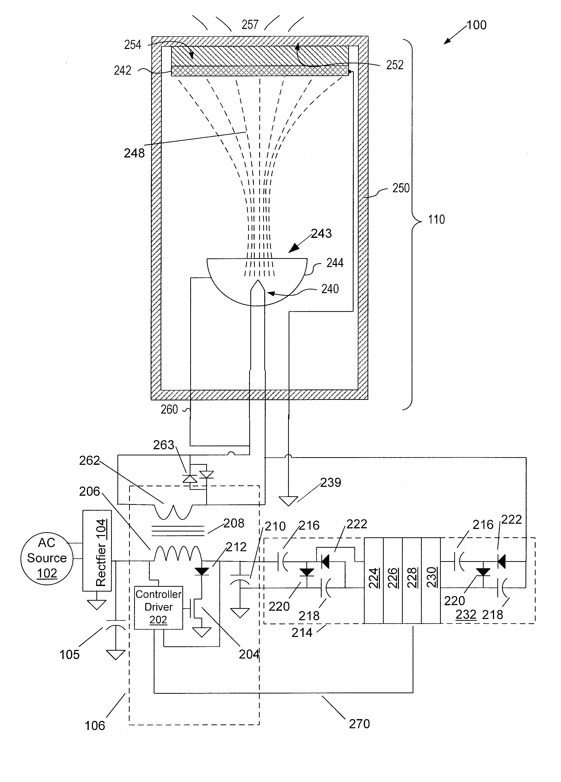
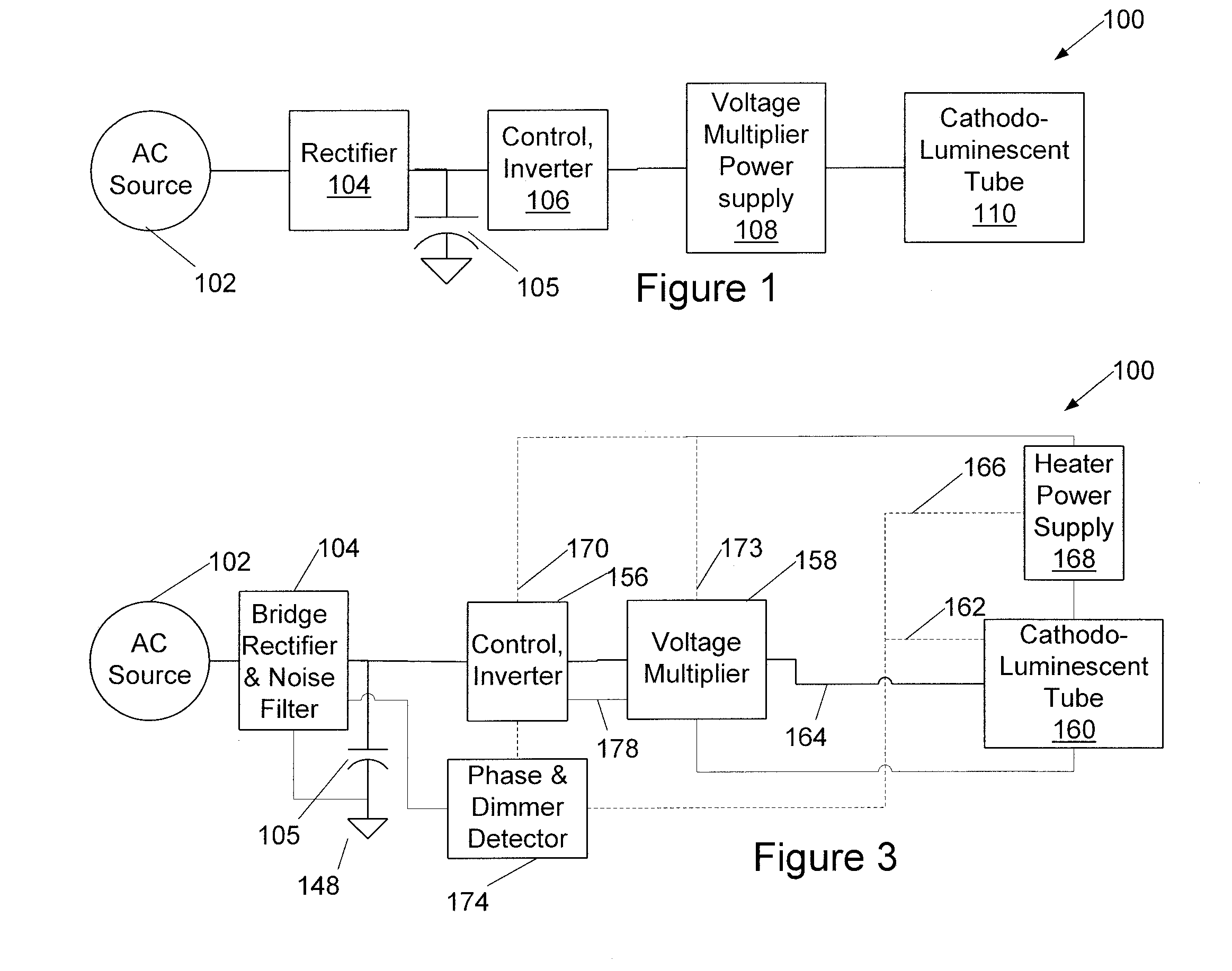
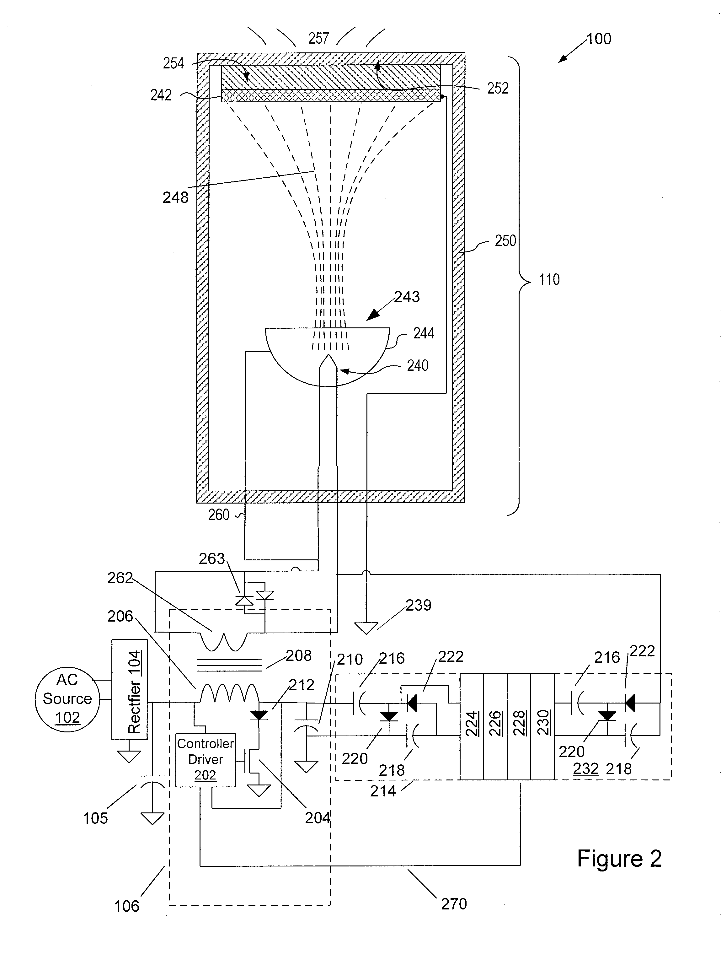
[0031]As shown in FIG. 1, a cathodoluminescent lighting system 100 (see FIGS. 1-4) is powered by an external AC power source 102. AC power from the power source 102 is rectified by a rectifier 104, which may be a bridge rectifier (see FIG. 3), into DC power and filtered by a capacitor 105. In embodiments operating from a 120-volt AC power source 102, a resulting DC voltage can be approximately 160 volts. Filtering components may also be present in the rectifier 104 to prevent undesirable emissions from being coupled back into the power source 102, and to protect the cathodoluminescent lighting system 100 from spikes and surges to AC power source 102. DC power is input to a controller-inverter unit 106, to provide high frequency AC power. High frequency AC power in turn feeds a voltage-multiplying rectifier 108 to provide high voltage suitable for powering a cathodoluminescent tube 110 and, in another example, low voltage to power a cathode heater of the cathodoluminescent tube 110 (...


PUM


Abstract

Electron sources for a cathodoluminescent lighting system are disclosed. An electron source is a broad-beam reflecting-type electron gun having a cathode for emitting electrons and a reflector and / or secondary emitter electrode and no grids. An alternative electron gun has a cathode having a heater welded to a disk, the disk having an emissive surface on a side facing a dome-shaped defocusing grid and an anode. A lighting system incorporating the electron sources has an envelope with a transparent face, an anode with a phosphor layer to emit light through the face and a conductor layer. The system also has a power supply for providing from five to thirty thousand volts of power to the light emitting device to draw electrons from cathode to anode and excite a cathodoluminescent phosphor, and the electrons transiting from cathode to anode are essentially unfocused. A power-factor-corrected embodiment is also disclosed.

Description

RELATED APPLICATIONS[0001]This application claims priority to provisional patent applications: U.S. Patent Application 61 / 096,665, filed Sep. 12, 2008; U.S. Patent Application 61 / 164,858, filed Mar. 30, 2009; and U.S. Patent Application Ser. No. 61 / 164,866, filed Mar. 30, 2009, the disclosures of which are incorporated herein by reference.[0002]This application is also a continuation-in-part of U.S. patent application Ser. No. 11 / 969,840, filed Jan. 4, 2008, which claims priority to U.S. Patent Application Ser. No. 60 / 888,187, filed Feb. 5, 2007, the disclosure of which is incorporated herein by reference.FIELD OF THE INVENTION[0003]The present application is related to a lighting device having a defocused cathode-ray device and driving circuitry, and also to a lighting device having an enhanced power factor.BACKGROUND OF THE INVENTION[0004]Typically, lamps used for general lighting utilize a tungsten filament that is heated to generate light. This process, however, is generally ine...

Claims


Application Information

Patent Timeline
Patent Type & Authority Applications(United States)
IPC IPC(8): H01J1/15H05B37/02
CPCH01J61/56H05B41/14H01J63/06
Inventor HERRING, RICHARD N.HUNT, CHARLES E.SKUPIEN, THOMASHASILIK, TOMASJELINEK, VIKTORVANCIL, BERNARD K.
Owner VU1 CORP
Why Eureka
Try Eureka